💬 WhatsApp Chat

Fine Blanking Machine & Die Troubleshooting Guide

Diagnostic reference for the ten most common fine blanking faults, with likely causes, step-by-step diagnostics, and corrective actions from four decades of press experience.

Diagnostic Framework

How to Use This Guide

Fine blanking is a triple-force process. When a fault appears, the root cause is rarely where you first look. This guide follows a symptom-first methodology: identify what you see, narrow down from probable causes, and follow verification steps in order. Each entry includes specific measurements, thresholds, and corrective actions. See our fine blanking technology overview for process fundamentals.

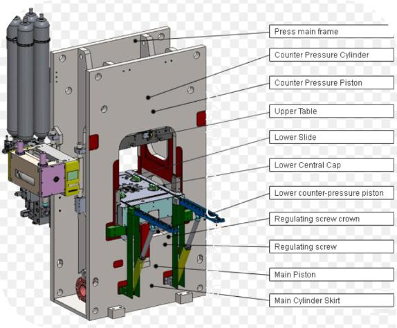
Fine blanking press internal structure showing hydraulic circuits, V-ring ram, counter-piston, and CNC control system
Fault 1

Burr Appearing on the Cut Edge

The most frequently reported fault. A burr — typically 0.05–0.3 mm of plastically deformed material protruding from the die side of the cut edge — indicates that material is being pushed through the die clearance rather than cleanly sheared.

Diagnostic StepWhat to CheckThreshold / Action
1. Burr location mappingMeasure burr height at 8 points around the part perimeter using a micrometer or optical comparatorUniform burr → die/V-ring wear. Localized burr → alignment or clearance issue
2. V-ring profile inspectionRemove the die, inspect V-ring tip with a profile projector. Check for rounding, chipping, or height lossRounding radius > 0.1 mm or height loss > 0.05 mm → regrind or replace V-ring insert
3. F2 (blank-holder) pressure verificationCompare current F2 setting against the original process parameter sheet. Check hydraulic pressure gauge under loadDrift > 5% from setpoint → inspect seals, proportional valve, and pressure transducer
4. Die clearance measurementUse feeler gauges or lead wire to measure actual clearance between punch and dieClearance > 0.5% of material thickness → die has opened from wear; regrind die plate and re-shim
5. Material batch verificationCross-reference current material certificate against the batch the die was originally tuned forYield strength difference > 30 MPa → re-tune F2 and F3 forces for the new batch
Most common cause: V-ring tip wear. A V-ring losing 0.05 mm tip height cannot fully impinge the material. Inspect and resharpen or replace.
Fault 2

Die Break — Fracture Band Replacing Clean Shear Edge

When the smooth-cut surface drops below 80% and a visible fracture band appears, the material is no longer being held in sufficient compression through the full cutting stroke. The fracture initiates at the punch side and propagates downward.

Diagnostic StepWhat to CheckThreshold / Action
1. Measure fracture percentageInspect the cut edge under 10x magnification. Calculate the ratio of smooth shear to total edge length< 80% smooth → insufficient compression during cut
2. F3 (counter-pressure) verificationCheck counter-piston pressure setting and actual delivery under loadF3 < 15% of F1 → increase counter-pressure; if unable to reach setpoint, inspect counter-piston seals
3. Material hardness checkMeasure Rockwell hardness of current material batch; compare to die design specificationHardness exceeds spec by > 3 HRC → material out of range; either source correct material or increase F3 and reduce cutting speed
4. Cutting speed verificationCheck CNC-programmed cutting speed against process parameter sheetSpeed > 15 mm/s → reduce to 5–10 mm/s for harder materials to prevent adiabatic softening
5. Die clearance re-verificationConfirm clearance is appropriate for current material thickness and strengthClearance too large for harder material → re-shim to 0.3–0.4% of sheet thickness
Often-missed cause: Material thickness variation within the coil. A coil with ±0.05 mm variation changes the required clearance. Verify with a micrometer at multiple positions.
Fault 3

Press Not Reaching Rated Tonnage

The CNC displays a tonnage reading 10–30% below the programmed setpoint, or the press trips out on low-force alarm before completing the cutting stroke. This is a hydraulic system fault, not a die problem.

Diagnostic StepWhat to CheckThreshold / Action
1. Hydraulic fluid conditionPull an oil sample. Check viscosity, water content (Karl Fischer), and particulate contamination (ISO 4406 cleanliness code)Viscosity outside ±10% of spec, water > 200 ppm, or cleanliness worse than ISO 20/18/15 → change fluid and filter
2. Pump delivery testRun pump at rated RPM with no load. Measure flow rate against pressure curveFlow < 90% of rated → pump wear; check internal leakage by measuring case drain flow
3. Proportional valve responseCommand a step input on the main relief valve. Monitor pressure rise time on oscilloscopeRise time > 200 ms or overshoot > 10% → valve spool wear or contamination; clean or replace valve
4. Cylinder seal integrityPressurize main cylinder, close isolation valve, monitor pressure decay over 5 minutesPressure drop > 5% in 5 min → internal seal leakage; schedule seal replacement
5. Tonnage sensor calibrationApply a calibrated load cell to the press bed and compare against the machine's tonnage displayReading error > 3% → recalibrate or replace load cell; do not assume the press is underperforming if only the sensor reads low
Critical note: If the press is over 15 years old with multiple hydraulic issues, the root cause is likely cylinder seal degradation across the system. Plan a full seal replacement.
Fault 4

Hydraulic Pressure Drop During Stroke

System pressure drops mid-stroke, causing the cutting force to decay as the punch penetrates the material. The part may show a transition zone where the edge quality deteriorates halfway through the cut.

Diagnostic StepWhat to CheckThreshold / Action
1. Accumulator pre-chargeCheck nitrogen pre-charge pressure on all hydraulic accumulators with the system depressurizedPre-charge below 60% of system pressure → recharge or replace bladder/bag
2. Pump cavitation checkListen for cavitation noise during high-flow demand (cutting stroke). Check suction filter and reservoir oil levelCavitation noise or suction pressure below 0.5 bar absolute → clean filter, top up reservoir, inspect pump inlet
3. Heat exchanger performanceMonitor oil temperature rise across a 1-hour production run. Check cooling water flow and temperature differentialOil temp > 55°C or rise > 15°C/hour → clean heat exchanger, verify cooling water supply
4. Relief valve settingCheck main relief valve setting under dynamic load. Some valves drift from vibrationSetting below system pressure by > 5% → adjust lock nut, replace if spring fatigue suspected
Thermal cause: Oil viscosity drops above 55°C, reducing V-ring clamping force. Check oil temperature and cooling system.
Fault 5

V-Ring Marks Inconsistent Across Part Perimeter

The V-ring impression depth varies around the part — deep on one side, shallow or absent on the other. This indicates uneven V-ring engagement, typically caused by press frame deflection, die alignment drift, or V-ring insert wear on one side.

Diagnostic StepWhat to CheckThreshold / Action
1. V-ring impression measurementMeasure V-ring mark depth at 8 positions around the part using a depth gaugeVariation > 0.03 mm → uneven engagement; proceed to parallelism check
2. Press bed parallelismPlace a precision straight edge across the bed. Check parallelism between ram and bed at four corners using dial indicatorsParallelism error > 0.02 mm/m → check gib adjustment, frame condition, or shimming
3. Die shoe flatnessRemove die set. Check die shoe mounting surfaces for wear, corrosion, or distortionFlatness > 0.01 mm deviation → regrind die shoe or re-shim mounting
4. Guide pillar clearanceCheck guide pillar and bushing for wear. Measure clearance with dial indicatorClearance > 0.005 mm → replace bushings; oversized clearance allows die lateral shift under asymmetric load
Asymmetric loading: Non-symmetric parts create lateral force that displaces the V-ring. Add a counter-balance or use a double V-ring configuration.
Fault 6

Part Flatness Out of Specification

Parts emerge from the die with visible bow or warp, exceeding the 0.05 mm flatness specification. This fault is most common on thin materials (< 2 mm) and high-strength alloys where internal stress release causes post-cut deformation.

Diagnostic StepWhat to CheckThreshold / Action
1. Flatness measurementPlace part on a granite surface plate. Measure gap with feeler gauges at multiple pointsGap > 0.05 mm on parts < 2 mm thick → counter-pressure insufficient
2. F3 (counter-pressure) verificationConfirm F3 is set to 20–25% of F1 for thin materials. Check actual deliveryF3 below 15% of F1 → increase to 20–25%; if F3 cannot reach setpoint, inspect counter-piston seals and pressure circuit
3. Strip feeder tensionExcessive strip tension induces bending moments during the cut. Check feeder back-tension settingTension above material yield in the strip width → reduce feeder hold-down pressure
4. Material internal stressCut a test coupon from the coil. Measure flatness of the raw strip before blankingStrip itself is not flat → adjust straightener rolls; if coil-set persists, material supplier issue
5. Slug ejection timingIf the counter-piston retracts before the V-ring releases, the part springs back without supportCNC timing sequence error → verify ejection delay is programmed to match V-ring retraction
Material note: HSLA and work-hardening stainless steels generate higher cutting resistance, requiring increased counter-pressure.
Fault 7

Slug Stuck in Die Cavity

The finished part fails to eject from the die after the cutting stroke. The counter-piston cannot push it free, causing a press stop and potential die damage on the next stroke.

Diagnostic StepWhat to CheckThreshold / Action
1. Die wall conditionInspect die cavity walls for galling, material buildup, or coating delaminationGalling marks visible → polish die wall to Ra < 0.2 μm; consider PVD coating (TiCN or AlCrN) if material is adhesive (e.g., stainless, aluminum)
2. Counter-piston forceVerify counter-piston is delivering rated ejection force. Check for bent or worn ejector pinsPins bent or worn > 0.02 mm → replace pins; verify counter-piston full stroke
3. Die clearance checkInsufficient clearance causes the slug to expand and wedge in the die cavity under compressionClearance < 0.3% of material thickness → increase to 0.4–0.5%; too-tight clearance is as problematic as too-loose
4. Lubrication systemVerify lubrication delivery to die cavity. Check spray nozzle alignment and flow rateFlow rate below 50 mL/min or nozzles misaligned → clean nozzles, verify pump pressure, adjust spray pattern
Material adhesion: Austenitic stainless and aluminum alloys are prone to galling. Use coated punches (TiCN or CrN) and high-pressure lubrication.
Fault 8

Counter-Pressure Fluctuation

The F3 pressure reading oscillates ±5–15% during the cutting stroke, causing inconsistent flatness and edge quality across a production run. The CNC may log intermittent counter-pressure alarms.

Diagnostic StepWhat to CheckThreshold / Action
1. Counter-piston seal integrityPressurize counter-piston circuit, close isolation valve, monitor for pressure decayPressure drop > 3% in 2 min → seal replacement required; fluctuation often precedes total seal failure
2. Accumulator functionCheck accumulator on counter-pressure circuit for correct pre-charge and bladder conditionNo pressure cushioning → recharge or replace accumulator bladder
3. Proportional valve responseCommand step input on counter-pressure valve. Monitor response on oscilloscopeOscillation or lag > 100 ms → valve contamination or wear; clean valve, check spool for scoring
4. CNC PID parametersReview CNC closed-loop control parameters for counter-pressure circuitOverly aggressive PID gain causes oscillation → reduce proportional gain, increase derivative time
Oil contamination: Counter-pressure circuits use small-orifice proportional valves that clog easily. Check oil cleanliness if fluctuations appear.
Fault 9

Strip Feed Misalignment

The strip feeder advances material off-pitch, causing pilot pin misregistration or partial blanks.

Diagnostic StepWhat to CheckThreshold / Action
1. Feed pitch verificationMeasure actual feed length over 10 consecutive strokes. Compare to programmed pitchError > ±0.05 mm → feeder calibration or mechanical issue
2. Feeder roll conditionInspect feeder roll surface for wear, glazing, or material pickup. Check roll grip pressureWear depth > 0.1 mm or glazing → regrind or replace rolls; verify grip pressure setting
3. Decoiler tension profileLog feed error against coil position (start, middle, end of coil). Check decoiler brake/tension controlError increases as coil diameter shrinks → decoiler tension not compensating; adjust tension profile or install automatic tension control
4. Straightener adjustmentCheck if coil-set is fully removed before the feeder. Residual curl causes the strip to lift off the feed lineVisible curl in strip entering feeder → adjust straightener rolls; for heavy-gauge material, increase roll penetration
5. Pilot pin engagementInspect pilot pins for wear. Verify pin diameter vs. pilot hole clearancePin wear > 0.02 mm or clearance > 0.05 mm → replace pins; worn pins cannot correct feed error
Coil effect: As a coil unwinds, back-tension changes by 3x. A servo-driven decoiler with diameter feedback compensates automatically; mechanical brakes cannot.
Fault 10

CNC Alarm Codes — Common Interpretations

HF-series presses use a CNC controller that logs alarm codes by circuit and fault type. Below is a reference table for the most frequent codes encountered in production. Always cross-reference with the specific alarm text displayed on the HMI.

Alarm PatternLikely MeaningFirst Action
F1 Low Force / Tonnage Not ReachedMain blanking force below setpoint at bottom of strokeCheck hydraulic pressure, pump delivery, main cylinder seals (see Fault 3)
F2 Pressure DeviationV-ring clamping force drifted beyond tolerance band during strokeInspect V-ring cylinder seals, proportional valve response (see Fault 1, Step 3)
F3 Pressure FluctuationCounter-pressure oscillation exceeded ±5% of setpointCheck counter-piston seals, accumulator, PID tuning (see Fault 8)
Oil Temperature HighHydraulic oil exceeded 55°C thresholdStop production, verify cooling water flow, clean heat exchanger (see Fault 4, Step 3)
Emergency Stop CircuitSafety circuit interrupted — could be light curtain, door interlock, or e-stop buttonWalk the safety circuit: check light curtain alignment, door switch engagement, and e-stop button reset state
Recurring alarms: If the same code appears 3+ times per shift after corrective action, the fault is likely in the control system, not the mechanical components. Request a CNC diagnostic.
When to Stop Troubleshooting

When to Call for Professional Inspection

This guide provides diagnostic starting points, not a substitute for hands-on inspection. If you encounter any of the following, continued operation risks compounding damage:

Safety-Circuit Alarms

Repeated e-stop, light curtain, or door interlock alarms. Do not bypass safety circuits — shut down and isolate the press.

Hydraulic Fluid Contamination

Oil analysis worse than ISO 22/20/17 or visible water ingress. Flush and replace fluid before resuming production.

Multiple Concurrent Faults

Two or more faults appearing simultaneously suggests a systemic issue — frame distortion, foundation settling, or major hydraulic degradation. Requires comprehensive inspection.

Need help? Contact Helen at +86-13062870081 or WhatsApp. See our service overview.

Need Expert Help With Your Fine Blanking Press?

Whether you are troubleshooting an HF-series press or a legacy Feintool, Mori, or Schuler machine, our engineering team can help you diagnose the root cause and implement the correct fix — not just a temporary patch.

💬