💬 WhatsApp Chat

Fine Blanking Post-Processing Services

A fine blanked part rarely ships as just a blank. Most programs require at least one downstream step — deburring, heat treatment, surface finishing, or traceability marking — before the part reaches assembly. We coordinate these steps as one integrated process, not a chain of separate vendor handoffs.

Integrated Post-Processing

Why Post-Processing Belongs in the Original Process Plan

Fine blanking produces parts with 100% smooth shear edges, IT7–8 dimensional tolerance, and flatness under 0.05 mm straight off the press. This eliminates milling, drilling, and reaming. But the part is rarely “done” at the press exit. A brake caliper piston needs surface hardening. A seat recliner gear needs shot peening for fatigue life. A transmission clutch plate needs surface coating for corrosion resistance. These post-processing steps interact with the blanking process in ways that buyers often underestimate — heat treatment can distort a flatness that was previously in spec, and coating thickness must be accounted for on parts with tight fit tolerances.

Coordinating these steps with the shop that blanked the part in the first place eliminates the finger-pointing that occurs when a dimensional issue surfaces after a separate vendor’s process step. When we control both the blanking and the post-processing, we can pre-compensate in die design — for example, adding 0.02 mm clearance to accommodate a 15 μm zinc-nickel coating, or adjusting blanking force to leave residual compressive stress that survives a subsequent quench.

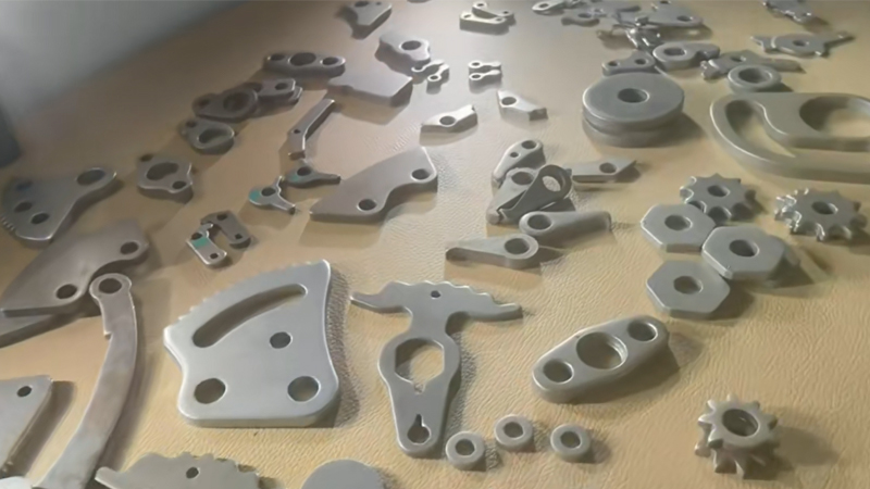
Fine blanked precision parts undergoing post-processing including deburring and surface finishing
Deburring Methods

Deburring: Removing the Last Remnant of Conventional Thinking

Fine blanking produces a minimal burr compared to conventional stamping — typically under 0.05 mm at the die-roll zone. But “minimal” is not “zero,” and for sealing surfaces, bearing seats, or assembly-critical edges, even this micro-burr must be removed. Three methods cover virtually every fine blanking application.

Vibratory Deburring

Parts are placed in a vibrating tub with abrasive media (ceramic, plastic, or steel pellets) and a compound solution. The media rubs against the parts, removing burrs and rounding edges uniformly. Cycle times range from 15 minutes for light deburring to 2 hours for aggressive radius creation. This is the workhorse for batch-processed fine blanked parts — gears, brackets, plates — where the burr is small and consistent. Vibratory deburring is specified when the drawing calls out a radius edge or a deburr requirement without a specific Ra target.

Brush Deburring

Rotating nylon or wire brushes pass over the part surface, targeted at the cut edge. Unlike vibratory, which treats the entire part, brush deburring is directional and can reach specific edges without affecting functional surfaces. This is critical for parts with polished or coated functional zones where media contact would damage the finish. Brush stations can be integrated inline with the press output conveyor, allowing continuous deburring at cycle rates of 20–40 SPM. Typical burr removal: 0.02–0.08 mm per pass.

Thermal Deburring (TEM)

Parts are placed in a sealed chamber pressurized with an oxygen-hydrogen mixture. ignition creates a 2500–3000 °C thermal wave lasting 20–40 milliseconds. Burrs, being thin and high-surface-area, oxidize completely while the bulk part mass absorbs the heat without metallurgical change. Thermal deburring is the only method that reliably removes burrs from internal cross-holes, blind pockets, and undercuts inaccessible to mechanical media. It is specified for hydraulic valve plates, fuel injector components, and complex internal geometries.

Integration insight: For inline production lines, vibratory stations are placed at the press exit conveyor, processing parts batch-while-running. Brush deburring can be fully synchronized with the press stroke, requiring no batch buffer. Thermal deburring is necessarily an offline batch process — parts are collected and processed in lots of 50–200, with a cycle time of 3–5 minutes per lot. See our deburring and polishing guide for detailed process selection criteria.
Fatigue & Hardness

Shot Peening and Case Hardening: Engineering the Edge Zone

The fine blanked shear edge is work-hardened during the cutting stroke — hardness at the cut surface typically increases 30–50% above the bulk material. But for many applications, this is not enough. Safety-critical parts need engineered surface properties that go beyond what blanking alone delivers.

Shot Peening

Shot Peening for Fatigue Life

Shot peening bombards the part surface with small steel, ceramic, or glass beads at controlled velocity (Almen intensity 0.15–0.45 mm A). The impact creates a layer of compressive residual stress 0.1–0.5 mm deep, which dramatically improves fatigue life by suppressing crack initiation. For fine blanked parts, shot peening is most commonly applied to seatbelt anchors, seat recliner teeth, and valve spring retainers — components subjected to cyclic loading where fatigue failure is the primary failure mode. Published studies show 5–10x improvement in fatigue limit for peened versus unpeened carbon steel parts.

Coverage must reach 98%+ for automotive specifications (typically per AMS 2430 or customer-specific standards). Peening is applied after blanking and deburring but before any coating, as the compressive layer must be the outermost metallurgical feature. Over-peening — intensity above 0.6 mm A — can cause surface micro-cracking and actually reduce fatigue life, which is why intensity and coverage are controlled to specification, not maximized.

Shot peening and case hardening equipment integrated with fine blanking production line
Surface Engineering

Case Hardening: Carburizing and Induction

Hardening MethodCase DepthSurface HardnessBest Suited For
Gas Carburizing0.3–1.5 mm58–62 HRCGears, splines, cam plates — parts needing deep case for tooth flank durability
Induction Hardening0.5–3.0 mm55–60 HRCLocalized hardening of specific zones — gear teeth, bearing journals, wear tracks
Nitriding0.1–0.4 mm900–1200 HVStainless and alloy parts requiring high surface hardness with minimal distortion
Carbonitriding0.1–0.6 mm55–62 HRCThin parts and low-carbon steels needing hard, wear-resistant surface
Distortion management: Heat treatment is the most common source of post-blanking flatness loss. Gas carburizing at 925°C followed by oil quench can warp a part that left the press at 0.03 mm flatness to 0.15 mm or worse. We pre-compensate in die design by mapping distortion vectors from test runs and adjusting blanking clearances and V-ring geometry. For parts with tight post-hardening flatness requirements (under 0.05 mm), we recommend induction hardening over through-carburizing, as the localized heat input minimizes thermal distortion.
Surface Finishing

Surface Finishing: From Polishing to Electroplating

Mechanical Polishing

When the fine blanked shear edge Ra of 0.4 μm is not sufficient — typically for hydraulic seal surfaces or optical-grade components — mechanical polishing brings the surface to Ra 0.1 μm or better. Belt polishing and lapping are the two primary methods. Belt polishing removes 0.01–0.03 mm of material; lapping with diamond compound can achieve mirror finish with minimal stock removal, critical for maintaining dimensional integrity.

Electroplating

Zinc-nickel (Zn-Ni) plating at 8–15 μm is the automotive industry standard for corrosion protection on fine blanked parts, passing 720+ hours of salt spray per ASTM B117. For higher corrosion classes, zinc flake (Magni 560, Delta Protekt) coatings provide 1000+ hours of protection with low hydrogen embrittlement risk. Electroplating thickness must be factored into the blanking die clearance — a 12 μm Zn-Ni coating adds 0.024 mm to the effective diameter of a hole, which can push an H7 tolerance out of spec if not pre-compensated.

Black Oxide

A conversion coating formed by immersing the part in a hot alkaline nitrate bath (140–150°C), producing a magnetite (Fe3O4) layer 0.5–1.5 μm thick. Black oxide provides mild corrosion resistance (24–96 hours salt spray with supplementary oil dip) and a matte black aesthetic. It is specified for internal components — gear teeth, spline internal surfaces — where dimensional change must be zero and a thin, uniform coating is preferred over bulkier electrodeposited layers.

Phosphate Coating

Zinc or manganese phosphate creates a crystalline layer 2–15 μm thick that serves as a base for subsequent paint, lubricant, or break-in coating. Manganese phosphate is specifically used on fine blanked gear teeth and sliding surfaces for its anti-galling and lubricant-retention properties. The coating does not change part dimensions measurably and is applied at 70–90°C, eliminating heat-treatment distortion risk entirely.

Final Steps

Cleaning, Packaging & Traceability Marking

Cleaning & Packaging

Cleaning for Shipment

Before packaging, parts undergo ultrasonic cleaning (40 kHz, 60°C) in a mild alkaline solution to remove pressing oil, deburring compound, and any plating bath residues. Cleanliness is verified to automotive standard VDA 19 or ISO 16232 — particulate counts on functional surfaces must stay below specified limits (typically 1–5 mg per part for safety-critical components). After cleaning, parts are dried in a forced-air tunnel and immediately sealed to prevent oxidation.

Traceability Marking

Every safety-critical part receives a unique identifier — typically a 2D Data Matrix code (10×10 mm) laser-etched on a non-functional surface. The code encodes: part number, material lot, die serial, press machine ID, production date, and shift. This enables full backward traceability from the assembled vehicle back to the specific coil of steel. Laser marking depth is controlled to 0.02–0.05 mm — deep enough to survive e-coating and painting, shallow enough to avoid stress concentration on functional edges. Dot-peen marking is used as an alternative for parts where the thermal input of laser marking is undesirable.

Cleaning, packaging, and traceability laser marking process for finished fine blanked parts
Integration

Inline Integration with the Press

The most efficient post-processing setups integrate directly with the production line rather than moving parts to a separate finishing cell. A typical inline configuration places a brush deburring station at the press exit conveyor, followed by a wash station and a laser marking cell. Parts flow through without manual handling until they reach the packaging station.

Process StepInline or BatchCycle TimeWhen to Use
Brush DeburringInline2–3 sec/partExternal edges, continuous flow, single-direction burr
Vibratory DeburringBatch (inline buffer)15–120 min/batchAll-over deburr, edge radiusing, batch quantities
Thermal DeburringOffline batch3–5 min/lotInternal burrs, complex geometry, cross-holes
Shot PeeningBatch (inline buffer)5–15 min/batchFatigue-critical safety parts, cyclic loading
Heat TreatmentOffline batch2–8 hoursAll parts requiring hardness above blanked hardness
ElectroplatingOffline batch30–60 min/batchCorrosion protection, automotive spec compliance
Laser MarkingInline1–2 sec/partTraceability, all safety-critical parts
Architecture insight: The choice between inline and batch is not just about speed — it is about process control. Inline steps are controlled by the press PLC and run at synchronized cycle rates, ensuring every part receives identical processing. Batch steps introduce variability (lot-to-lot chemical concentration drift, media wear in vibratory tubs) that must be controlled through separate SPC systems. For PPAP and FAI documentation, inline processes are easier to evidence because each part has a timestamp and machine parameter record. Learn more about the fine blanking technology that makes these integration choices possible.

Need Post-Processing Coordinated with Your Fine Blanking Program?

Send us your part drawing and required post-processing specifications. We will scope a complete process plan — from blanking through deburring, heat treatment, finishing, marking, and packaging — as one coordinated project.

💬