💬 WhatsApp Chat

Fine Blanking for Electric Motor Stator & Rotor Core Laminations

Every EV traction motor contains 200–500 thin silicon steel laminations stacked into a core. A 0.005 mm burr on each lamination creates interlaminar short circuits that increase eddy current losses by 5–15%. Fine blanking eliminates that burr — and that loss.

EV Motor Manufacturing

The 0.005 mm That Separates Fine Blanking from Stacking Failures

An electric motor's stator and rotor cores are not solid metal. They are stacks of 200–500 individual laminations, each 0.2–0.5 mm thick, separated by a thin insulation coating. This lamination structure exists for one reason: to interrupt the eddy current paths that would otherwise generate massive resistive losses in the solid iron core. The thinner the laminations and the better the insulation between them, the lower the eddy current loss and the higher the motor efficiency.

Here is the critical engineering constraint: any burr on a lamination edge pierces the insulation coating of the adjacent lamination when the stack is compressed. A burr of just 0.01 mm — invisible to the naked eye — creates a metallic contact point between adjacent laminations. This contact forms a short circuit, allowing eddy currents to flow between layers. The result is localized heating, efficiency loss, and in severe cases, thermal runaway that burns out the motor winding insulation.

Conventional stamping produces burr heights of 0.03–0.10 mm on silicon steel laminations — far above the threshold where interlaminar shorting begins. Fine blanking produces burr heights under 0.005 mm, which sit below the insulation coating thickness and do not penetrate the interlaminar barrier. This single parameter — burr height — is the make-or-break specification that determines whether a lamination process is viable for EV traction motors.

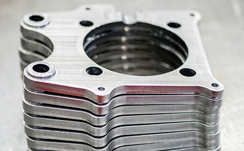
Fine blanked electric motor stator and rotor core laminations showing burr-free shear edges for interlaminar insulation
Lamination Fundamentals

What Motor Laminations Are and Why Burr Matters

A motor lamination is a precision part — not a simple stamped disk. Understanding its geometry and failure modes is essential to understanding why fine blanking is the correct process.

Lamination Geometry

Each lamination is a thin electrical steel sheet (0.2–0.5 mm) stamped into a complex shape: stator laminations feature tooth projections with slot openings for winding insertion; rotor laminations feature pole pieces, air-gap surfaces, and sometimes internal cooling channels. The tooth geometry determines the motor's magnetic circuit — tolerances of ±0.02 mm on slot width directly affect motor performance and noise.

Silicon Steel Grades

Motor laminations use non-oriented electrical steel, graded by core loss (W/kg at 1.5T, 50 Hz). Common grades range from 50W1300 (economy, 13 W/kg) to 50W400 (high-efficiency, 4 W/kg) and down to 35W250 (premium efficiency, 2.5 W/kg). Higher silicon content (up to 3.2%) reduces core loss but increases material hardness and brittleness, making fine blanking more challenging.

The Burr → Short Circuit → Loss Chain

The failure mode is simple and devastating: burr on lamination edge → burr pierces insulation coating of adjacent lamination when stack is compressed to 2–5 MPa → metallic contact creates eddy current path → eddy current losses increase motor core loss by 5–15% → motor runs hotter and less efficiently → insulation degrades faster → motor fails prematurely. The only prevention is burr control at the blanking stage.

Head-to-Head

Fine Blanking vs Conventional Stamping for Laminations

The difference in burr, edge quality, and motor performance is not incremental — it is the difference between a motor that meets its efficiency target and one that fails it.

ParameterFine BlankingConventional Stamping
Edge Quality100% smooth shear surface30–70% shear + fracture zone
Burr Height<0.005 mm0.03–0.10 mm
Die Roll (edge rounding)<0.02 mm0.05–0.15 mm
Flatness per Lamination<0.02 mm0.05–0.15 mm
Slot Width Tolerance±0.02 mm±0.05–0.10 mm
Interlaminar Short Circuit RiskNegligible (burr < coating thickness)High (burr pierces coating)
Motor Core Loss ImpactBaseline (optimal)+5–15% core loss increase
Die Clearance (% of t)2–4%5–10%
Die Life (silicon steel)5–10 million hits per regrind1–3 million hits
Insulation Coating DamageMinimal (smooth edge)Significant (fracture zone chips coating)
Efficiency insight: For a 150 kW EV traction motor with 350 laminations, conventional stamping's 10% core loss increase translates to approximately 150W of additional heat dissipation — enough to require a larger cooling system and reduce the motor's continuous power rating. Fine blanking eliminates this penalty at the source by controlling burr to under 0.005 mm. For more on the fine blanking principle, see our technology overview and EV lightweighting fine blanking guide.
Stacking & Insulation

Stacking, Interlocking & Insulation Coating

Producing a good lamination is only half the battle. The lamination must also be designed for automated stacking, and its insulation coating must survive the blanking process intact.

Interlocking is the technique that allows laminations to auto-assemble into a rigid stack without adhesives or welding. Each lamination is stamped with a small dimple (projection) on one face and a corresponding recess on the opposite face. When laminations are stacked, the dimple of one lamination engages the recess of the next, creating a mechanical interlock that holds the stack together under the compressive force of the motor housing. In fine blanking, this interlock feature is formed in the same stroke as the outer profile — the progressive die includes a forming station that creates the dimple while the blanking punch shears the lamination outline.

Insulation coating on motor laminations is categorized by grade. C-3 coating is an organic varnish applied after blanking, providing 5–15 Ω·mm² interlaminar resistance. C-5 coating is an inorganic ceramic-based coating applied before blanking, offering superior thermal stability (up to 500 °C) and 50–200 Ω·mm² resistance. Fine blanking's smooth shear edge preserves C-5 coating integrity significantly better than conventional stamping — the fracture zone of a stamped edge creates micro-cracks in the pre-applied coating, reducing effective insulation resistance by 30–60%.

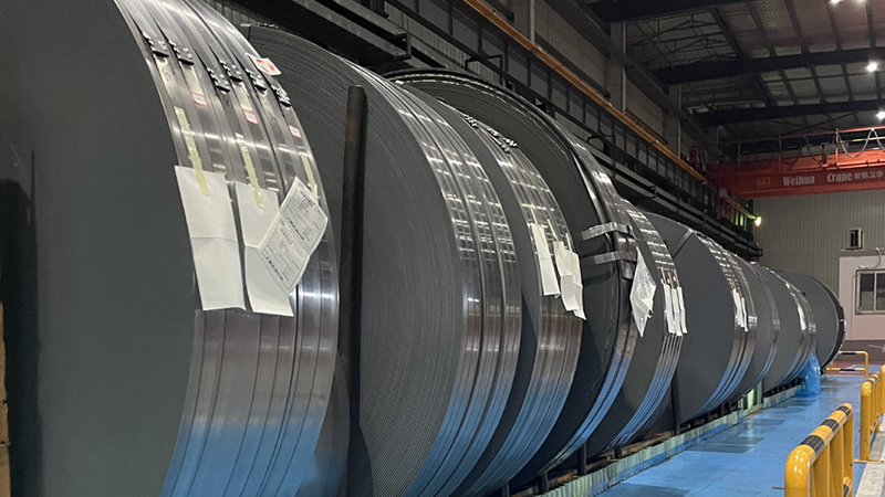
Silicon steel motor lamination sheets with interlocking dimple features and surface insulation coating
Die Engineering

Progressive Die Design for Lamination Production

Motor lamination production uses progressive fine blanking dies with 3–5 stations, each performing a specific operation on the strip as it advances through the die.

1

Station 1: Pilot Holes

The first station pierces pilot holes at precise locations in the strip. These holes engage pilot pins in subsequent stations to position the strip to ±0.01 mm — critical for maintaining slot-to-OD concentricity and tooth-to-tooth spacing across the lamination.

2

Station 2: Slot Pierce

The second station pierces the stator slot openings or rotor internal features. For stator laminations, this means piercing 12–48 individual slot openings in a single station — each slot a precision shape with tolerances of ±0.02 mm. The pierce punches are mounted in a guided plate to maintain alignment.

3

Station 3: Interlock Form

The third station forms the interlocking dimple using a small embossing punch. The dimple geometry — typically 0.1 mm height, 1.5 mm diameter — must be consistent to ±0.01 mm across millions of parts, as variation in interlock height causes stack density variation and motor core dimensional instability.

4

Station 4: Outer Profile Blank

The fourth station shears the outer profile of the lamination. This is the fine blanking station: V-ring engages the strip, counter-pressure holds the lamination flat, and the blanking punch shears the profile with 100% smooth-cut edge. Die clearance is held to 2–4% of material thickness.

5

Station 5: Part Ejection

The final station ejects the finished lamination from the die, either by air blast or mechanical extractor. The lamination drops onto a stacking mandrel that accumulates the stack — 200–500 laminations per motor — directly from the press output.

Die life note: Silicon steel (50W400–50W1300) is relatively soft and non-galling compared to alloy steels, allowing die life of 5–10 million hits per regrind with carbide tooling. However, the 2.5–3.2% silicon content increases work-hardening at the shear edge, so die edge sharpness must be maintained — a dull edge produces die-roll above 0.05 mm, degrading lamination flatness. Coating the die with TiN or AlCrN extends life by 2–3× and maintains edge sharpness longer. See our materials guide for silicon steel specifications.
Press & Market

Press Requirements & EV Motor Applications

Motor lamination production demands specific press characteristics — high speed, precision bottom-dead-center (BDC) control, and moderate tonnage.

ParameterSmall Motor LaminationsEV Traction Motor Laminations
Material50W800–50W1300 silicon steel50W250–50W400 silicon steel
Thickness0.35–0.50 mm0.20–0.35 mm
Laminations per Motor200–300300–500
Required Press Tonnage50–100T100–200T
Production Speed (SPM)60–12060–100
BDC Precision Required±0.02 mm±0.01 mm
Recommended HS-FINEB PressHF-200 (200T)HF-320 (320T)
Annual Lamination Demand10M–20M per model40M–100M per model
EV market scale: A single EV model producing 200,000 motors per year requires 60–100 million laminations annually (300–500 laminations per motor). At 80 SPM, a single press produces approximately 38 million laminations per year at 60% uptime — meaning 2–3 press lines serve an entire vehicle program. Our HF-200 and HF-320 triple-action hydraulic presses deliver the BDC precision, counter-pressure control, and V-ring force necessary for burr-free lamination production at these volumes. The CNC hydraulic system allows independent programming of all three forces, optimizing V-ring and counter-pressure for each silicon steel grade and thickness.

Ready to Fine-Blank Motor Laminations?

Send us your lamination drawings, silicon steel grade, and annual volume target. We will evaluate progressive die feasibility, recommend the optimal press configuration, and provide a per-lamination cost estimate at your production scale.

💬