A technical deep-dive into the dimensional, geometric and surface tolerances achievable with fine blanking — from IT6–IT9 dimensional accuracy to 100% shear edge quality, flatness, die-roll control and perpendicularity — with the factors that determine where on the tolerance spectrum your part lands.
Fine blanking achieves dimensional tolerances from IT6 to IT9 per ISO 286 depending on material type, thickness, part feature and die condition. This is a significant improvement over conventional stamping, which typically achieves IT12–IT14. The tolerance range is broad because it is not a single number — it depends on multiple interacting factors that must be understood to specify realistic tolerances on part drawings.
For a 4 mm thick part in mild steel (C45), fine blanking typically holds ±0.02 mm on a 25 mm feature (IT7). For the same material at 8 mm thickness, the achievable tolerance drops to ±0.04 mm (IT8). Thinner materials and softer grades achieve tighter tolerances; thicker materials and harder grades require wider tolerances. The key is to specify tolerances that are achievable with the process, not tolerances that force the supplier into 100% inspection or selective assembly.

Fine blanking produces excellent flatness because the counter-pressure holds the material flat during shearing, preventing the bending and distortion that occurs in conventional stamping. Typical flatness for a 50 mm diameter part in 3 mm mild steel is less than 0.1 mm — 5–10x better than conventional stamping. For larger parts or thicker materials, flatness is proportional to the span: a 100 mm part in 6 mm material typically holds flatness within 0.2 mm.
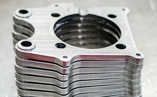
The defining characteristic of fine blanking is 100% shear (smooth-cut) edge — no tear zone, no fracture surface. The entire edge is produced by shearing, giving a surface roughness of Ra 0.2–0.4 μm. This eliminates secondary machining (milling, shaving) for most functional edge applications. The edge quality is consistent across the entire cutting line, including complex contours and internal features.
Die-roll is the rounded edge formed on the die side of the cut — the material flows plastically at the cutting edge before shearing begins. Die-roll is typically 5–15% of material thickness. It is controlled by V-ring geometry (the indentation ring that clamps the material), counter-pressure level, and die clearance. Higher counter-pressure reduces die-roll; sharper V-ring geometry reduces die-roll; tighter die clearance reduces die-roll. The trade-off is that excessive counter-pressure can cause die chipping.
Fine blanking achieves perpendicularity (edge-to-surface angle) of less than 0.5°, compared to 2–5° for conventional stamping. This near-perpendicular edge is critical for functional surfaces like gear teeth, braking surfaces and seating faces. Burr on the punch side is typically less than 0.1 mm and is controllable by optimizing die clearance (0.3–0.5% of material thickness is optimal). Burr can be further reduced by secondary deburring operations.

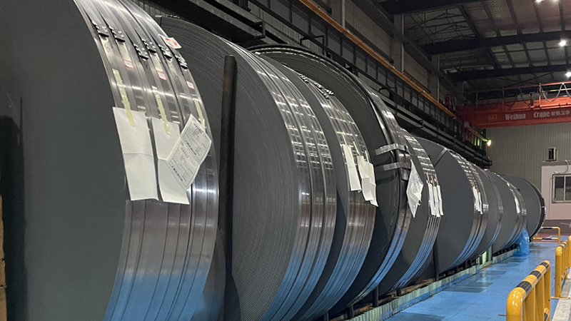
Softer materials achieve better tolerances because they flow more uniformly during shearing. Mild steel (C45, 16MnCr5) at 150–200 HB achieves IT6–IT7 consistently. Stainless steel (304, 316L) at 180–230 HB achieves IT7–IT8. High-strength steels (S700MC, S950MC) at 250–320 HB achieve IT8–IT9. Aluminum and copper alloys generally achieve IT7–IT8. The material’s work-hardening behavior also affects die life and edge quality.
Thinner materials achieve tighter tolerances. At 1–3 mm, IT6–IT7 is routine. At 3–6 mm, IT7–IT8 is typical. At 6–12 mm, IT8–IT9. Beyond 12 mm, tolerance capability degrades further due to the increased shearing force and the greater volume of material that must flow plastically at the cutting edge. The press force required also scales with thickness squared.
Die clearance (the gap between punch and die cutting edges) is the single most critical parameter for edge quality and dimensional accuracy. The optimal clearance is 0.3–0.5% of material thickness — for 4 mm material, that is 0.012–0.020 mm. Too little clearance causes galling and die chipping; too much clearance causes tear zones, burr and dimensional drift. Clearance must be uniform around the entire cutting line, which requires precision die manufacturing and rigid press guidance.
The V-ring (also called the ring jaw or stinger) indents the material around the cutting line before the punch contacts the surface. Its geometry — tooth angle (typically 30–45°), tooth height (0.3–1.5 mm depending on material thickness), and distance from the cutting edge (typically 1.0–1.5 times material thickness) — determines how effectively the material is clamped. Higher counter-pressure (typically 20–40% of blanking force) further reduces die-roll and improves flatness.
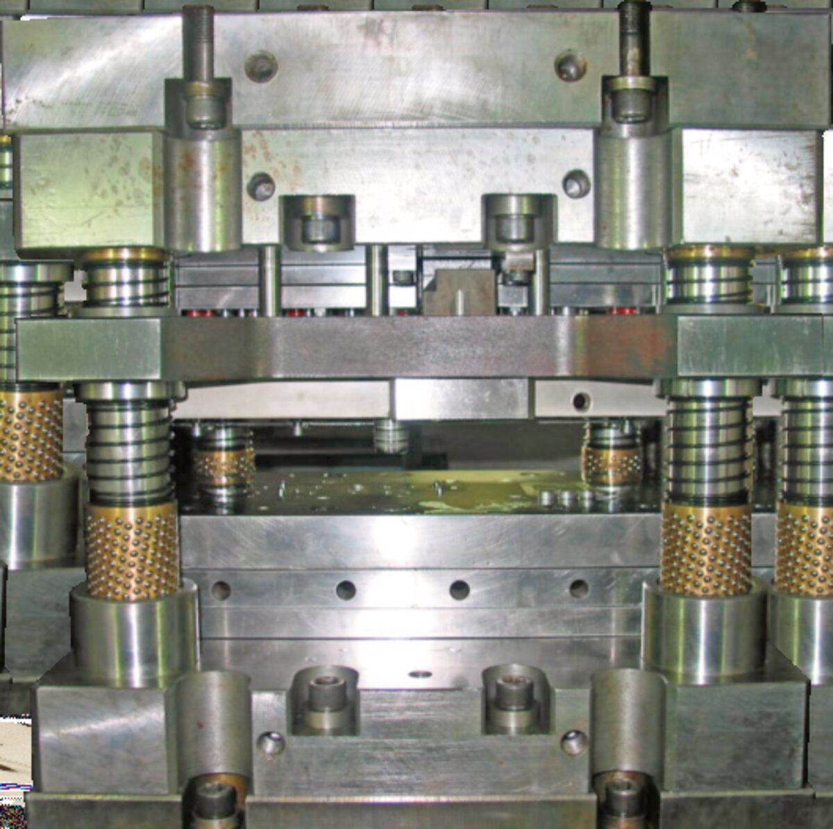
Fine blanking uses slow shear speeds (5–15 mm/s) compared to conventional stamping (100–500 mm/s). The slow speed allows the material to flow plastically rather than fracturing, which is what produces the 100% smooth-cut edge. Speed control is critical — if the ram accelerates through the shear zone, the edge quality degrades. This is why hydraulic presses with proportional speed control, or servo presses with programmable motion profiles, are preferred for fine blanking.

The following reference values represent typical achievable tolerances with a well-maintained fine blanking press, properly designed die, and controlled material supply. Actual tolerances should be validated on the specific application.
Mild Steel (C45, 16MnCr5, ~180 HB): At 1–3 mm thickness: IT6 (±0.008–0.012 mm on 10–25 mm features), die-roll 5–8%, flatness <0.05 mm per 50 mm. At 3–6 mm: IT7 (±0.012–0.025 mm), die-roll 8–12%, flatness <0.10 mm. At 6–12 mm: IT8 (±0.025–0.050 mm), die-roll 10–15%, flatness <0.15 mm.
Stainless Steel (304, 316L, ~200 HB): At 1–3 mm: IT7 (±0.012–0.020 mm), die-roll 8–12%. At 3–6 mm: IT8 (±0.020–0.040 mm), die-roll 10–15%. Stainless work-hardens during shearing, requiring higher press force and more frequent die sharpening.
HSLA Steel (S700MC, ~250 HB): At 2–5 mm: IT8 (±0.020–0.040 mm), die-roll 10–15%. At 5–8 mm: IT9 (±0.040–0.080 mm), die-roll 12–18%. HSLA requires higher counter-pressure and specialized die steels to maintain die life.
Aluminum (5052, 6061): At 1–3 mm: IT7 (±0.010–0.020 mm), die-roll 5–10%. At 3–6 mm: IT8 (±0.020–0.040 mm), die-roll 8–12%. Aluminum requires sharp die edges and specialized lubricants to prevent galling.
Coordinate measuring machines (CMM) with touch-trigger or scanning probes measure dimensional accuracy to ±0.001 mm. For production-floor verification, digital calipers and micrometers provide ±0.005 mm and ±0.001 mm respectively. CMM is used for first-article inspection (FAI) and PPAP submission; micrometers are used for in-process SPC.
Surface roughness testers (Mitutoyo SJ-210 or equivalent) measure Ra on the shear edge directly. Stylus instruments trace the edge surface and compute Ra per ISO 4287. For fine blanking, the target is Ra 0.2–0.4 μm on the shear surface. Optical profilometers provide non-contact measurement for delicate features.
Optical comparators and digital microscopes measure die-roll height, burr height and perpendicularity by projecting a magnified profile of the cut edge. Die-roll is measured as a percentage of material thickness; perpendicularity is measured as the deviation from 90° over the material thickness.
Send us your part drawing and material specification. Our engineers will assess achievable tolerances, recommend V-ring and counter-pressure parameters, and validate with a first-article sample.