💬 WhatsApp Chat

Gear Fine Blanking Solution

From module 0.5 spur gears to module 3 planetary carriers — fine blanking produces gear teeth with 100% shear flanks in a single stroke, eliminating hobbing for most automotive gear applications.

Fine Blanking for Gears

One Stroke, Complete Tooth Profile

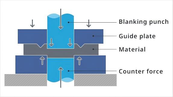
Fine blanking has transformed gear manufacturing by producing fully formed involute tooth profiles in a single press stroke. Where conventional stamping yields torn tooth flanks that require subsequent gear hobbing to achieve functional precision, fine blanking's triple-force system — V-ring impingement, counter-pressure and blanking force — shears the complete tooth profile with 100% clean cutting surface. The result is a gear blank that meets AGMA Q8-9 quality without any secondary tooth machining.

For automotive transmission gears, seat adjuster mechanisms, and planetary gear sets, this means a production route that eliminates the hobbing machine entirely. A 16MnCr5 spur gear at module 2.0, 4mm thick, that previously required blanking, drilling, and gear hobbing across three separate machines now comes off the fine blanking press in one stroke — tooth profile complete, bore pierced, mounting holes ready, and edge quality that meets functional requirements directly.

The economic case is straightforward: one press, one operator, one stroke per part versus a three-machine cell with multiple setups and intermediate handling. At production volumes above 50,000 parts per year, fine blanking reduces per-piece gear cost by 30-50% compared to the stamp-plus-hob route, while delivering superior tooth quality and dimensional consistency. For more on transmission gear applications, or to explore the full range of fine-blanked applications, visit our applications overview.

Key Differentiator: If your gear module is under 3, fine blanking eliminates hobbing entirely — the tooth profile comes off the press at final dimensional accuracy, ready for heat treatment and assembly.

Gear Types Suitable for Fine Blanking

Fine blanking is applicable to a broad range of gear geometries, each with specific die design considerations:

  • Spur gears (external teeth): The most common application. Straight-tooth profiles are the easiest to blank because the punch travels perpendicular to the gear face, and the involute profile is uniformly oriented in the blanking direction. Tooth-to-tooth accuracy of 0.01-0.015mm is routinely achieved.
  • Helical gears (limited helix angle): Helical teeth up to 15° helix angle can be fine-blanked, but the helix introduces lateral force components that increase die wear. Most automotive helical gears under module 2.5 with 10-12° helix fall within the fine blanking envelope.
  • Internal gears (ring gears): Fine-blanked from plate stock using a stinger (piercing punch). V-ring applied to the outer clamping plate. Internal gear blanks for planetary carriers are a high-volume application.
  • Planetary carriers: Complex geometries combining gear teeth, mounting bosses, and web patterns. Typically require multi-station progressive dies.
  • Rack teeth (linear gearing): Straight-tooth racks of any length within the press bed can be fine-blanked.
  • Sector gears (partial arc): Seat recliner mechanisms, door hinge quadrants, and similar partial-rotation components.
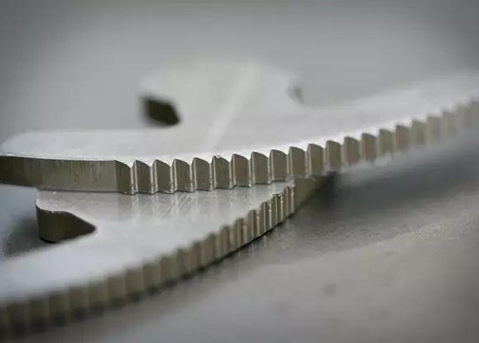
Fine-blanked gear component showing 100% shear tooth flanks
Module Range

Module 0.5 to 3.0: The Fine Blanking Envelope

The practical module range for fine blanking spans 0.5 to 3.0. Below module 0.5, the tooth depth is too shallow relative to the V-ring geometry, and the blanking force savings over conventional stamping do not justify the die cost. Above module 3.0, the tooth depth exceeds what the V-ring can effectively clamp — the material flows laterally during shearing, and the tooth tip tears rather than shears cleanly.

For modules above 3.0, the recommended approach is to fine blank the gear blank with all features except the tooth profile, then hob the teeth as a secondary operation. This hybrid route still saves material and reduces machining time compared to full billet machining, because the fine-blanked blank provides the outer diameter, bore, and mounting holes at final tolerance. Learn more about fine blanking die design principles that govern these limits.

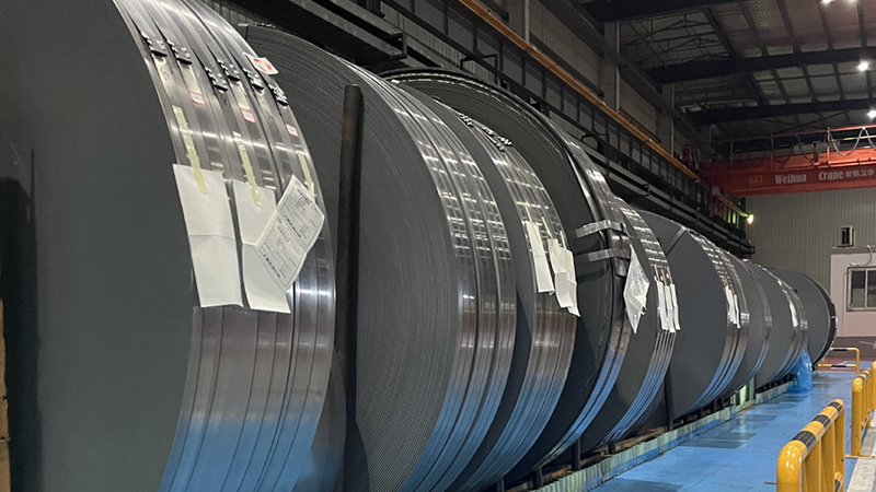
Case-hardening steel coil stock suitable for gear fine blanking
Module RangeTooth Depth (Approx.)FeasibilityTypical Application
0.5 - 1.01.0 - 2.0 mmExcellentSmall timing gears, instrument gears
1.0 - 2.02.0 - 4.5 mmOptimalTransmission gears, seat mechanisms
2.0 - 3.04.5 - 6.75 mmGood (requires careful V-ring)Planetary carriers, heavy-duty gears
3.0+6.75 mm+Not recommendedRequires post-blanking hobbing
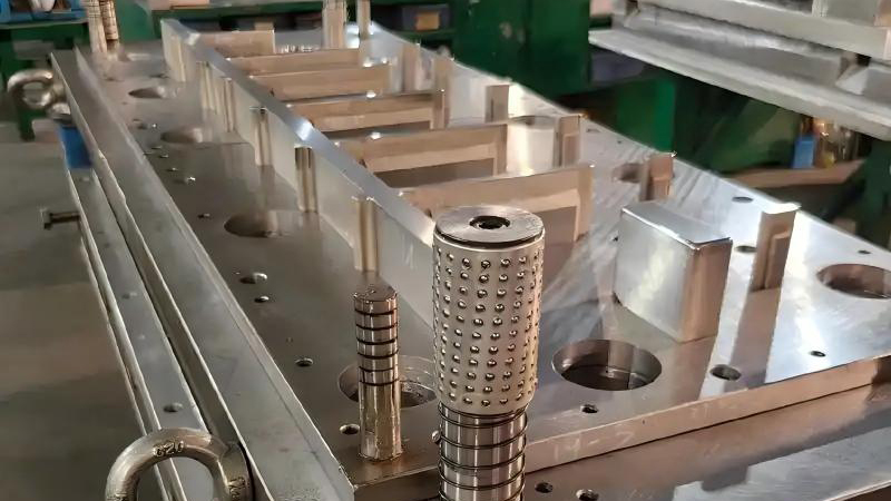
Fine blanking die with involute gear tooth profile

Involute Die Profile and Manufacturing

The involute tooth profile in the fine blanking die is manufactured by wire-EDM (electrical discharge machining) to achieve the dimensional accuracy required for AGMA Q8-9 gears. Wire diameter of 0.1-0.25mm allows the involute curve to be cut with a corner radius as small as 0.05mm, which is critical for the tooth root fillet that determines bending fatigue strength.

For production volumes above 100,000 parts, the wire-EDM cut punch and die plates are fitted with carbide inserts at the tooth flanks. Tungsten carbide (grade K20 or K30) provides 10-20x the tool life of hardened tool steel (D2 or D3) against the abrasive wear of case-hardening steels like 16MnCr5. The carbide insert is wire-EDM cut to the involute profile, then pressed into a steel holder with 0.002mm diametral clearance per tooth.

This clearance — approximately 0.5% of material thickness per flank — is the gap between the punch and die tooth profiles. Too little clearance causes the punch to gall against the die; too much and the tooth flank develops die-roll. Fine blanking's V-ring impingement holds the material so rigidly that even this minimal clearance produces a 100% shear surface on both tooth flanks simultaneously. See our die design page for detailed V-ring geometry specifications.

AGMA Quality

Fine Blanking vs Conventional Stamping

AttributeFine BlankingConventional Stamping
AGMA Quality ClassQ8-9Q5-6
Tooth Flank Surface100% shear (smooth)30-50% shear + tear zone
Die-Roll (% of thickness)<15%20-40%
Tooth-to-Tooth Error0.01-0.015mm0.03-0.05mm
Post-Blanking HobbingNot required (module ≤3)Required for all gears
Tooling ApproachV-ring + carbide insertStandard stamping die

The quality difference stems from two mechanisms. First, the V-ring impinges the material surface surrounding the gear, creating a hydrostatic stress state that prevents lateral material flow during shearing — this eliminates the tear-through zone that characterizes stamped gears. Second, the counter-pressure plate supports the tooth profile from below, preventing tooth tip deflection during the punch stroke. The combination produces a tooth profile where the entire flank is a clean shear surface with no torn metal and no dimensional variation from tooth to tooth.

Material Selection

Steels for Fine-Blanked Gears

16MnCr5

Case hardening steel (0.16% C, 1.0% Cr). The standard for automotive transmission gears. Carburize at 920°C for 4-8 hours, quench, temper at 180°C. Tooth surface 58-62 HRC, core 30-35 HRC. Excellent fine blanking behavior in the annealed state (max 160 HB).

20MnCr5

Higher carbon variant (0.20% C). Deeper case depth and higher core strength than 16MnCr5. Used for gears with higher torque requirements. Carburizing treatment similar to 16MnCr5. Fine blanking in annealed condition (max 180 HB).

25CrMo4

Chromium-molybdenum alloy steel for high-stress gears. Quench and temper to 28-32 HRC before fine blanking for optimal shear quality. Used in commercial vehicle transmissions and industrial gearboxes where impact loading is present.

C45

Medium carbon steel (0.45% C) for lower-load applications. Quench and temper to 25-30 HRC. Used for pump gears, agricultural machinery, and general-purpose power transmission where case hardening is not required. Most economical gear steel.

View Full Material Guide

Carbide tooth profiles deliver 150,000 to 300,000 strokes before requiring insert replacement or regrinding. The exact life depends on four factors: material hardness (higher hardness accelerates wear), lubricant quality (inadequate lubrication causes galling between carbide and steel), blanking speed (faster SPM increases thermal wear), and V-ring condition (a damaged V-ring allows material flow that abrades the tooth flank).

Die life monitoring is performed by sampling parts every 5,000 strokes and measuring tooth-to-tooth error with a gear inspection machine. When tooth-to-tooth error exceeds 0.02mm — or when visual inspection reveals the first signs of die-roll on the tooth tip — the die is pulled and the carbide inserts are reground or replaced. A well-maintained die set with replaceable carbide tooth inserts can produce over 1 million parts across multiple service cycles.

Carbide tooth insert detail in fine blanking die
150K-300K
Die Life (Strokes)
0.01mm
Tooth-to-Tooth Accuracy
<15%
Die-Roll (% of Thickness)
1M+
Total Parts per Die Set
Force Calculation

Press Force Sizing for Gear Blanking

Selecting the correct press tonnage requires calculating three force components: the blanking force (shearing the gear from the strip), the V-ring force (impinging the material surface), and the counter-pressure force (supporting the part from below).

The blanking force is calculated as: Fblank = P × τ × t, where P is the sheared perimeter (sum of all tooth profiles + outer diameter), τ is the material shear strength (typically 0.7-0.8 × tensile strength), and t is the material thickness. The V-ring force is typically 30-40% of the blanking force, applied through the ring protrusion on the stinger plate. The counter-pressure force is 20-30% of the blanking force, applied through the ejector on the die side.

Total force: Ftotal = Fblank + Fv-ring + Fcounter ≈ Fblank × 1.6

For example, a module 2.0 spur gear in 4mm 16MnCr5 with an 80mm pitch circle diameter requires approximately 320T total force — well within the HF-500's 500T capacity with 20% reserve.

Sizing tip: Always specify a press with at least 20% reserve capacity above the calculated force. This ensures consistent shear quality as the die wears and compensates for material hardness variations between heats.

Multi-Station Progressive Die Design

When a gear requires additional features beyond the tooth profile — mounting holes, keyways, counterbores, or lightening pockets — a multi-station progressive die combines all operations in a single strip feed. The gear is not cut free until the final station, which means the strip material serves as a carrier that transports the part through each station with precise pitch control.

A typical 4-station progressive die for an automotive transmission gear operates as follows:

  • Station 1: Pierce pilot holes (two holes establish strip position for subsequent stations)
  • Station 2: Pierce mounting holes and keyway (positioned relative to the pilot holes)
  • Station 3: Form counterbores and chamfers (material displacement, not removal)
  • Station 4: V-ring impingement and blank the gear (the gear is cut free with 100% shear flanks)

The progressive die approach reduces material waste by 15-25% compared to single-station blanking because the carrier strip is narrower (no need for a separate blank holder) and the nesting is tighter. At 30-40 SPM, a 4-station progressive die produces a complete gear every 1.5-2 seconds. See our production line page for full line configuration details.

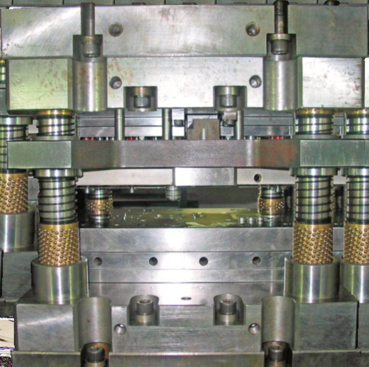
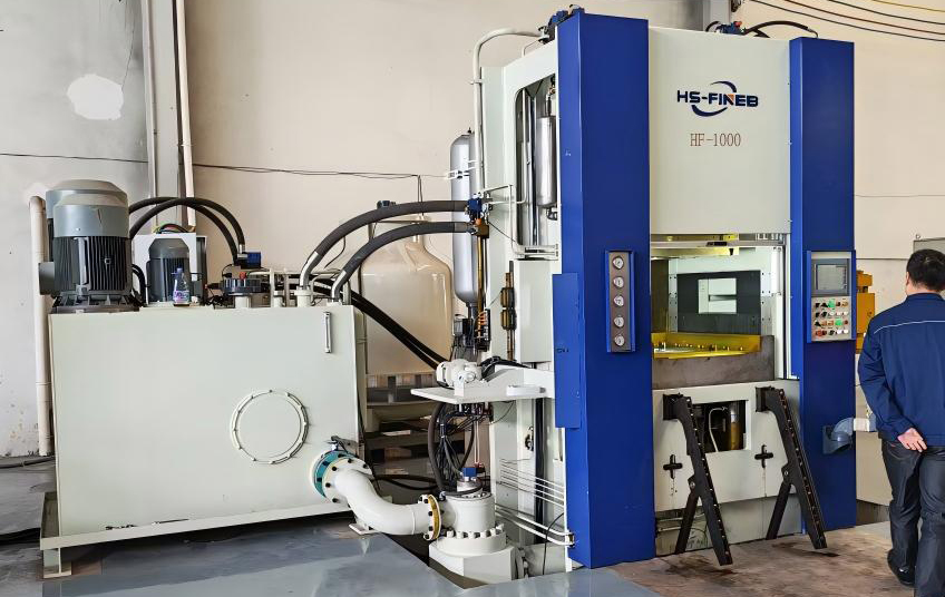
Fine blanking process producing gears on HF-series press
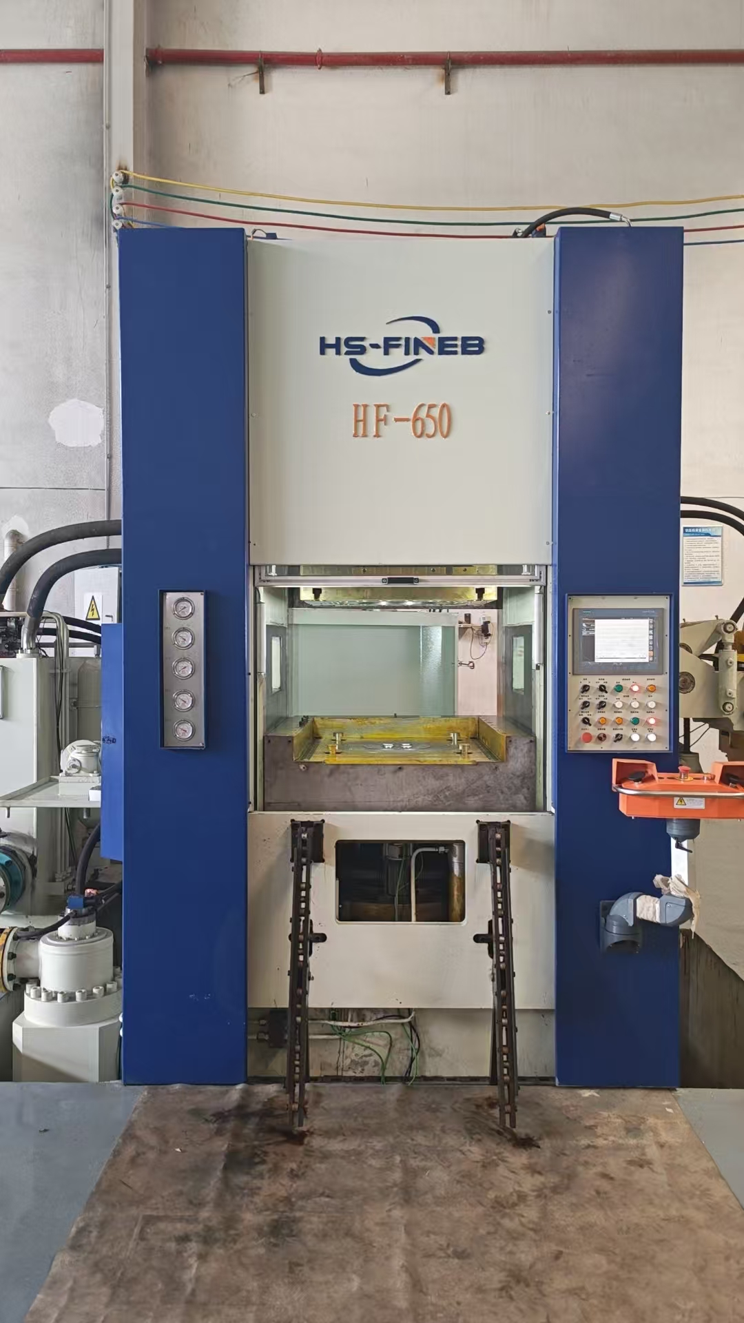
HS-FINEB HF-650 complete fine blanking press system capable of producing precision gears

Post-Processing: Shot Peening and Case Hardening

While fine blanking produces the gear tooth profile at final dimensional accuracy, two post-processing steps are typically required to achieve full functional performance:

Shot peening: The tooth root fillet is where bending fatigue failures initiate. Shot peening with S170 cast steel shot at 0.15-0.20mm Almen intensity introduces compressive residual stress that increases bending fatigue life by 20-30%, applied directly to the fine-blanked tooth with no surface preparation needed.

Case hardening (carburizing): For 16MnCr5 and 20MnCr5 gears, carburizing at 920°C for 4-8 hours produces 0.5-1.2mm case depth with 58-62 HRC surface hardness. Heat treatment distortion is minimal compared to machined gears because fine-blanked material has uniform grain flow and no machining-induced stress.

No hobbing is required for modules up to 3.0. For modules above 3.0, a light skiving hob pass removes 0.05-0.10mm from each tooth flank to correct any heat treatment distortion — but this is a finishing pass, not a tooth-generating operation. Learn more about surface finishing in our deburring and polishing guide.

Recommended Equipment

HS-FINEB Press Models for Gear Production

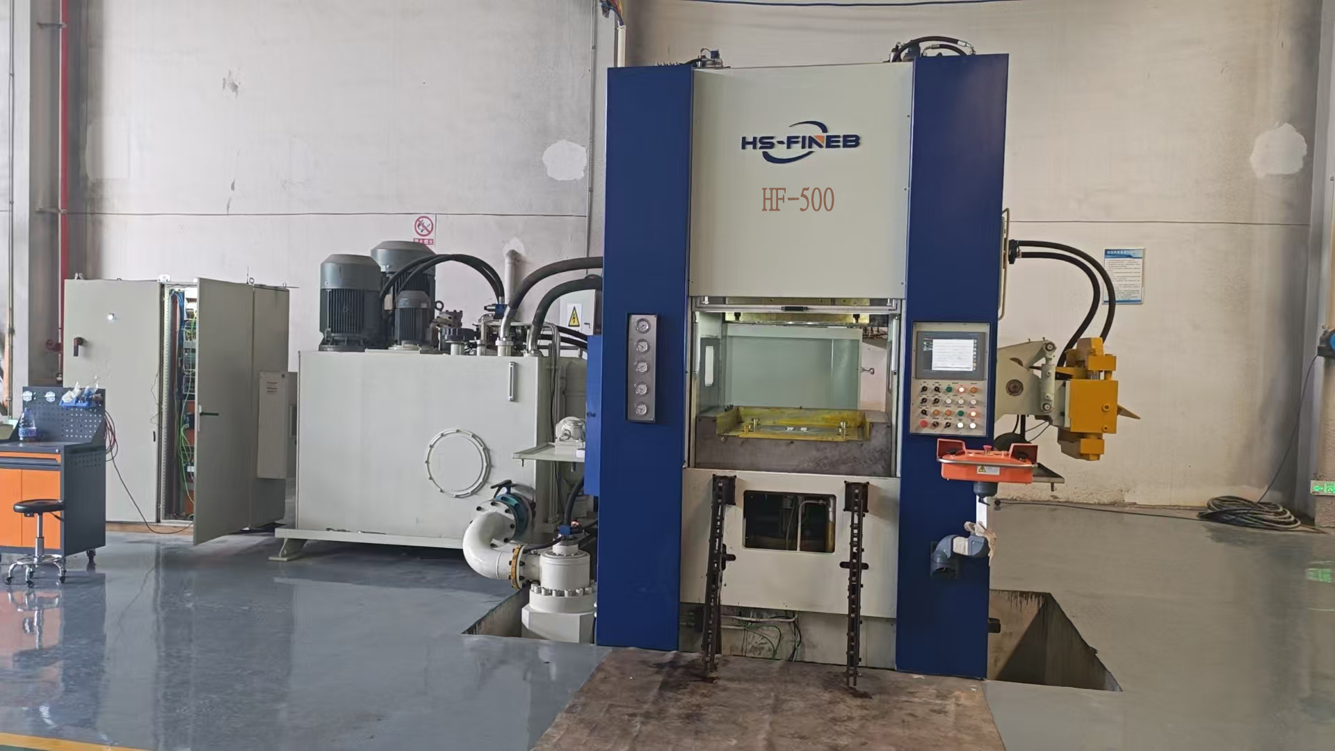
HF-500 fine blanking press for module 1-2 gears

HF-500 (500T)

For module 1.0-2.0 gears up to 100mm PCD. The 500T force handles 4mm thick 16MnCr5 gears with 20% reserve capacity. Ideal for passenger car transmission gears and seat adjuster mechanisms.

View HF-500
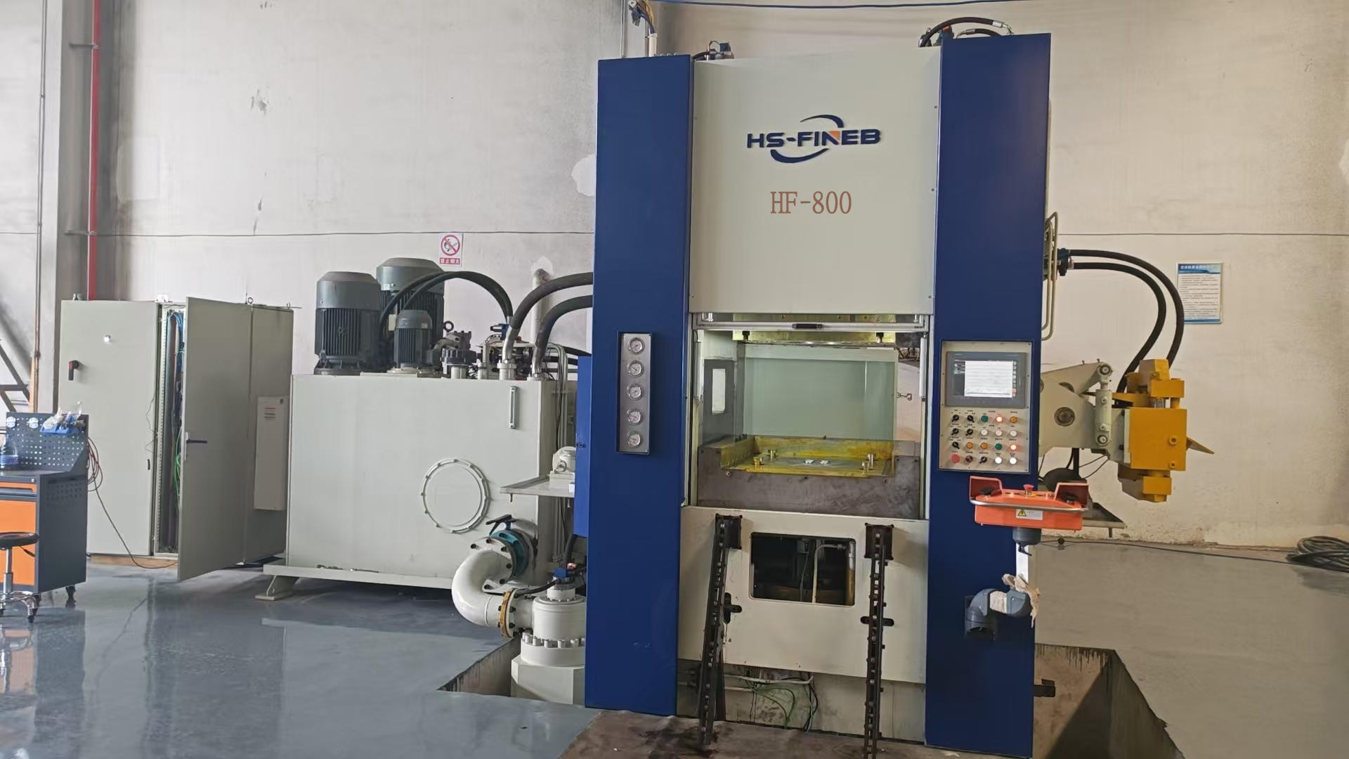
HF-800 fine blanking press for module 2-3 gears

HF-800 (800T)

For module 2.0-3.0 gears up to 150mm PCD. The 800T force accommodates thicker materials and larger diameters. Used for commercial vehicle gears and planetary carriers.

View HF-800
HF-1200 fine blanking press for large planetary carriers

HF-1200 (1200T)

For large planetary carriers and module 3.0 gears. The 1200T capacity handles the most demanding gear geometries, including multi-station progressive dies for high-volume production.

View HF-1200

Have a Gear Project to Evaluate?

Send your gear drawing, module specification, material grade and target production volume. Our engineers will assess fine blanking feasibility, calculate force requirements, design the die layout, and recommend the right HF-series platform for your gear application.

💬