The die determines 70% of part quality — we engineer it from first principles. V-ring geometry, cutting clearance, tool steel selection, and die life optimization explained.
A fine blanking press is only as good as the die inside it. You can put a perfectly tuned 400-ton triple-action press on the floor, but if the V-ring profile is wrong for the material, the cutting clearance is 2% instead of 0.5%, or the punch steel was heat-treated to 58 HRC instead of 60–62 — you will get fracture edges, excessive burr, and a die that wears out in 50,000 hits instead of 300,000.
Three design decisions drive 70% of the outcome: V-ring geometry (the impingement profile that prevents lateral material flow), cutting clearance (the gap between punch and die that controls burr height and edge tear), and tool steel selection (the material grade and hardness that determine edge retention and total die life).
Get these three right, and the fine blanking process delivers what it promises: 100% shear edges at IT7–8 tolerance, run after run, for hundreds of thousands of parts. Get them wrong, and no amount of press tonnage or counter-pressure will save the part.
Every fine blanking die lives or dies on these three parameters. They are decided before any steel is cut.
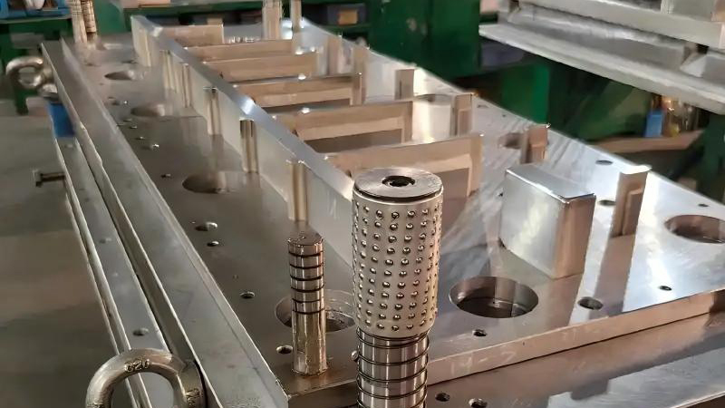
The V-ring is the serrated impingement ring that clamps the sheet flat around the die cavity. Two profiles dominate: the standard triangular V-ring (60° or 90° included angle) for most steels, and the ASV (asymmetrical V-ring) for high-strength materials where symmetric impingement causes uneven stress distribution.
V-ring height is tied to material thickness — typically one-third of sheet thickness. For 3 mm material, the V-ring stands 1.0 mm proud. For materials above 5 mm, a double-ring configuration (V-rings on both the guide plate and the die plate) is standard, impinging from both sides to prevent mid-plane material flow.
The gap between the punch cutting edge and the die cutting edge. In fine blanking, this clearance is extraordinarily tight: 0.5% of material thickness, compared to 5–15% for conventional stamping. For a 4 mm part, that means a clearance of 0.02 mm — measured and verified at four points around the die circumference.
Clearance directly controls burr height. Too much clearance and the material stretches before shearing, producing a rollover zone and a burr that exceeds 0.1 mm. Too little, and the punch galls against the die, accelerating edge wear and risking die chipping. The 0.5% rule is not a guideline — it is the threshold below which clean shear is physically maintained.
Three tiers of tool steel cover the full volume spectrum. D2 (DIN 1.2379) is the workhorse for medium-volume dies up to 300K hits — high carbon, high chromium, good wear resistance at 60–62 HRC. PM steel (CPM 3V or 9V) adds toughness through powder metallurgy, extending die life to 300K–600K hits and resisting the edge chipping that kills D2 in high-volume runs. Solid carbide inserts push past 1 million hits but require press rigidity beyond what entry-level machines deliver — carbide is unforgiving of frame deflection.
The selection rule is straightforward: match the steel to your expected total part volume, not your prototype volume. Re-cutting a D2 die at 300K hits costs less than starting with carbide for a 200K-run program.
Tool steel selection sets the baseline, but three treatments extend die life well beyond the as-hardened state:
| Tool Steel | Hardness | Typical Die Life |
|---|---|---|
| D2 (1.2379) | 60–62 HRC | 150,000–300,000 hits |
| PM Steel (CPM 3V/9V) | 60–62 HRC | 300,000–600,000 hits |
| Solid Carbide | 88–92 HRA | 1,000,000+ hits |
| D2 + TiCN Coating | 60–62 HRC | 400,000–600,000 hits |
A fine blanking die is not a disposable tool. With disciplined regrind management, the same die set produces parts for years.
The trigger is burr height, not hit count. Measure burr height every 10,000 hits using a calibrated optical comparator. When burr height exceeds 0.1 mm — or 10% of material thickness, whichever is smaller — the die is due for regrind. For D2 tooling on 4 mm C45 steel, this typically occurs at 50,000–100,000 hits. For PM steel with TiCN coating, the interval stretches to 150,000–250,000 hits.
Each regrind removes 0.1–0.3 mm from the punch and die cutting edges — just enough to reach fresh, unworn steel beneath the worn surface. The exact amount depends on edge condition: a clean regrind needs 0.1 mm; a die with micro-chipping requires 0.2–0.3 mm to remove the damaged zone entirely. After regrinding, re-shim the die stack to restore the original shut height.
Total die life = initial run + (regrinds × hits per regrind). A D2 die that runs 200K hits per regrind with 8 regrinds before the V-ring is consumed delivers 1.8 million total parts. A PM steel die at 400K hits per regrind with 6 regrinds reaches 2.8 million. Factor regrind cost (10–15% of new die cost) into the per-part tooling amortization.
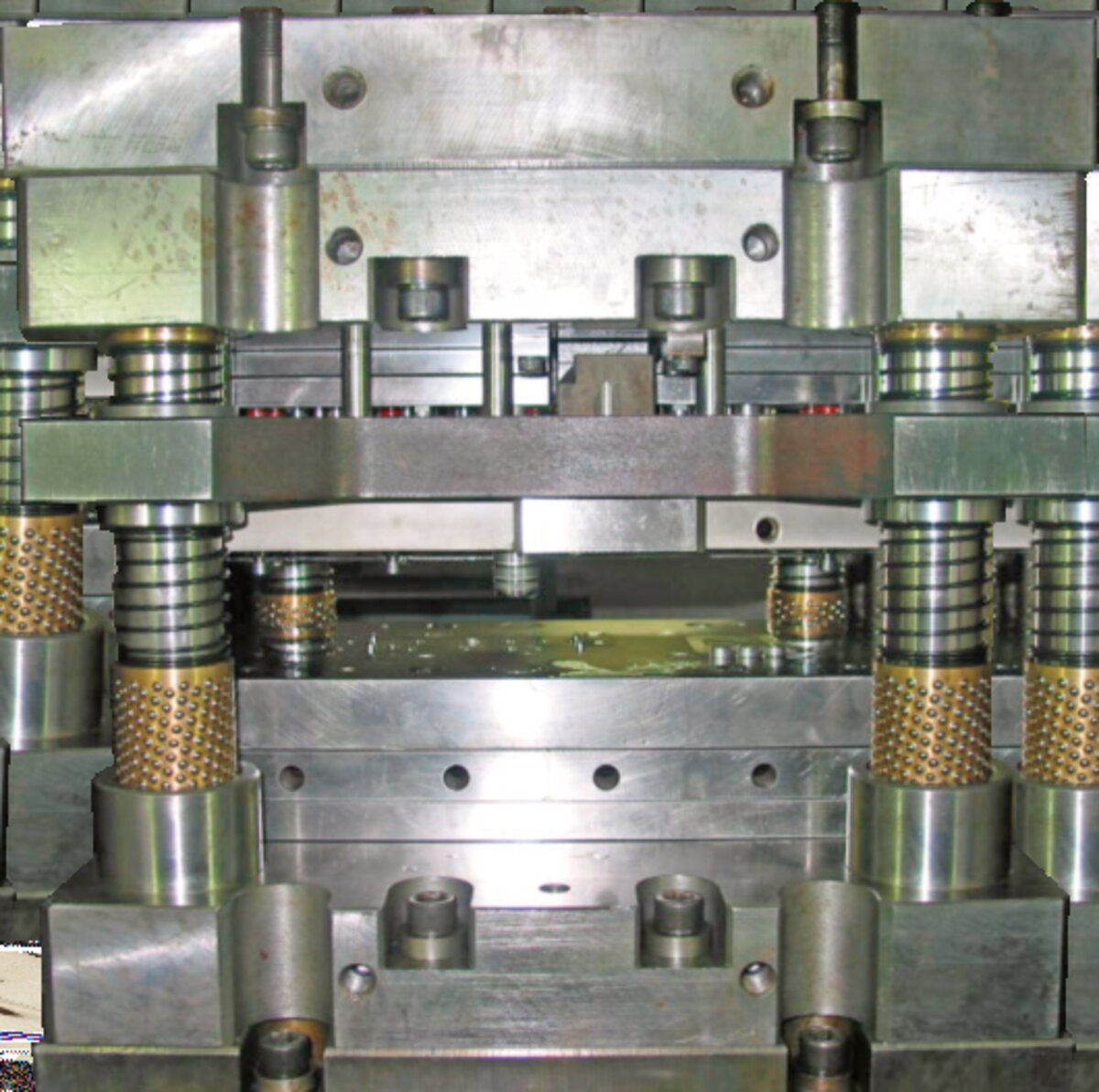
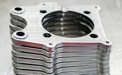
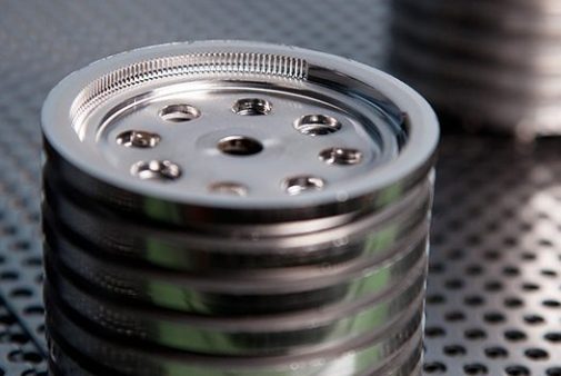
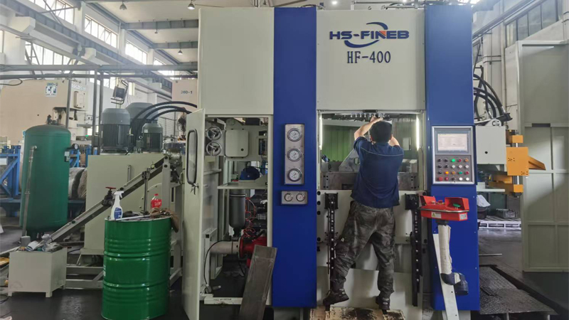
These parts were produced on HS-FINEB presses with dies engineered in-house. Each demonstrates a specific die design challenge solved.
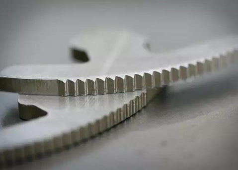
Transmission gear — 16MnCr5, 4 mm thick, double V-ring die, 100% shear on tooth flanks
Structural bracket — S500MC HSLA, 6 mm thick, elevated counter-pressure for crack prevention
Stainless component — 304 stainless, 2 mm thick, TiCN-coated die to resist work-hardening galling
Send us your part drawing and material spec. We will design the V-ring geometry, select the tool steel, and specify the coating strategy for your production volume.