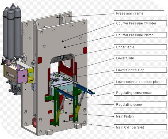
For parts with multiple features — holes, forms, partial cuts, and complex outer profiles — a progressive fine blanking die spreads the work across 4–8 stations as the strip advances, finishing a complete part on every press stroke. This is the tooling architecture behind high-volume, multi-feature precision parts.
A progressive fine blanking die distributes manufacturing operations across multiple stations along a continuous strip. At each press stroke, every station performs its operation simultaneously — one station punches pilot holes, the next pierces internal features, another forms a bend or coined step, and the final station blanks the outer profile with full V-ring engagement and counter-pressure. A finished part exits the die on every single stroke, delivering cycle rates of 25–60 strokes per minute.
The decision between progressive and compound die architecture comes down to part complexity and volume. Progressive tooling is the right call when a part has three or more distinct features that benefit from sequential operations, when monthly volume exceeds 30,000–50,000 parts, or when forming and blanking must be combined in a single tooling system. For simpler geometries — a single gear blank, a flat washer, a sealing plate — a compound die will typically deliver lower tooling cost and faster commissioning.
The engineering challenge in progressive die design is not any individual station. It is the strip layout: the sequence of operations, the material web that holds the strip together between stations, and the feed accuracy that positions each station relative to the last. Getting the strip layout wrong means strip breakage, misfeeds, and cumulative dimensional drift — problems that do not show up in any single station's design but doom the die in production.
A typical progressive fine blanking die uses 4–8 stations. Each station performs one operation, and the sequence must be engineered so that no operation compromises the material needed for subsequent stations.
| Station | Operation | Key Parameters | Engineering Rationale |
|---|---|---|---|
| 1 | Pilot hole piercing | 2 holes, Ø3–6 mm, at strip edges | Establishes strip positioning reference for all downstream stations; must precede every other operation |
| 2 | Internal feature piercing | Holes, slots, windows per drawing | Pierce internal features before outer profile cutting to maintain strip rigidity |
| 3 | Idle station | No operation | Provides die body strength between piercing and forming; allows material web to stabilize |
| 4 | Forming / coining | Bends, ribs, stepped thickness | Performed before final blanking so the formed feature is held flat during outer profile cut |
| 5 | Outer profile blanking (V-ring) | V-ring engages, counter-pressure active | The fine blanking stroke — 100% shear edge on the entire outer profile |
| 6 | Part-off / separation | Sever carrier web | Finished part drops or is extracted; scrap strip continues to discharge |
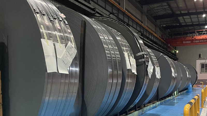
Material cost dominates the per-part economics of high-volume fine blanking. A well-optimized strip layout can raise material utilization from 45% to 70% or higher, directly reducing the coil cost per part by a third.
Utilization = (part area × parts per strip) ÷ (strip width × strip length) × 100%. For a 60 mm × 40 mm part on a 72 mm wide strip with 80 mm pitch, single-row utilization is approximately 42%. Double-row interlocked nesting on the same strip width raises this to 67%. The difference is €0.08–€0.15 per part on typical carbon steel coil — significant at 500K parts per month.
Single-row layout is simplest but wastes material on wide strips. Double-row interlocked nesting — where two parts share a common edge or are mirrored — can increase utilization by 20–30 percentage points. The trade-off is increased die complexity and tighter feed accuracy requirements, since both rows must register correctly through every station.
The material web between parts and at the strip edges must maintain sufficient strength to carry the strip through the die without distortion. Minimum web width is typically 1.5× material thickness for steel below 3 mm, increasing to 2× thickness for harder alloys. Carrier tabs connecting the part to the strip at the final station must be wide enough to survive transport but narrow enough for clean part-off — typically 2–3 mm.
Pilot holes are the positional backbone of a progressive die. Two holes, pierced at station 1 and located at opposite edges of the strip, are engaged by spring-loaded pilot pins at every subsequent station to register the strip position to within ±0.02 mm. A single pilot hole provides rotational registration only; two holes provide full X-Y positioning and angular control.
Pilot hole diameter is typically 3–6 mm for strip widths up to 120 mm. The holes must be positioned outside the part profile so they remain in the scrap strip after part-off. If the part geometry does not permit external pilot holes, internal pilot holes that become features in the finished part can be used, but this ties positioning accuracy to a feature that may have its own tolerance requirements.
Idle stations — stations where no operation occurs — serve three engineering purposes: they provide die body strength between heavy piercing and forming operations, they create space for material web stabilization, and they allow maintenance access to adjacent stations without disassembling the entire die. A 6-station die with 2 idle stations (8 total stations) may run more reliably than a tightly packed 6-station die with no idle positions.
Scrap strip analysis is the final validation of strip design. The scrap strip — the skeleton remaining after all parts are cut — must be strong enough to feed through the die discharge without buckling, and its weight per meter must be within the coil feeder’s handling capacity. A scrap strip that breaks mid-run causes immediate production stoppage.
Die clearance and V-ring configuration are not uniform across all stations in a progressive die. Each station’s clearance is calculated independently based on the operation it performs, the material being cut, and the feature geometry.
| Station Type | Clearance (% of t) | V-Ring Configuration | Force Distribution |
|---|---|---|---|
| Pilot hole piercing | 1.0–2.0% | No V-ring (non-functional edge) | Blanking force only |
| Internal feature piercing | 0.5–1.0% | No V-ring (internal features) | Blanking force + counter-pressure |
| Forming / coining | N/A (no cutting) | V-ring on forming station | Forming force + V-ring hold-down |
| Outer profile blanking | 0.5% | V-ring on die plate (single-ring for t < 5 mm) | Blanking + V-ring + counter-pressure |
| Outer profile blanking (thick) | 0.5% | Double V-ring (plate + die, for t ≥ 5 mm) | Blanking + double V-ring + counter-pressure |
Die clearance is calculated as a percentage of material thickness (t). For the outer profile blanking station, clearance is held at 0.5% of t — the tightest practical clearance that maintains 100% shear. For internal piercing stations where edge quality is less critical, clearance can be relaxed to 1.0–2.0% to reduce tonnage and extend punch life. The die designer must also account for material springback and work-hardening behavior, which can shift the effective clearance during production.
Progressive dies are the workhorse tooling for multi-feature parts produced at automotive volumes. These are the part families where progressive architecture consistently outperforms compound or single-station approaches.
Automotive seat recliner plates combine multiple mounting holes, a cam profile, gear teeth, and rivet holes in a single part. A 6–8 station progressive die produces these at 30–45 strokes per minute, with the cam profile and gear teeth formed at intermediate stations and the full outer profile fine-blanked at the final station. See our seat recliner solution for a detailed case study.
Seat belt retractor components — locking plates, sensor brackets, and webbing guide plates — require multiple precision holes, formed tabs, and a clean outer profile. Progressive tooling delivers these at 40–60 strokes per minute with IT7–8 tolerance on all functional features. The strip layout typically uses 5–7 stations with one idle station for die body strength.
High-density electronic connector strips with dozens of precision slots and contact features per part are a natural fit for progressive dies. Station counts of 8–12 are common, with each station piercing one row of contacts. Material is typically phosphor bronze or beryllium copper at 0.3–1.0 mm thickness, requiring specialized V-ring geometry tuned to thin-gauge non-ferrous alloys.
Send us your part drawing and target volume. We will evaluate whether a progressive die or compound die is the better fit for your geometry, material, and production volume — and recommend the press, feed line, and station layout to match. Our production line capabilities cover the full range from HF-200 to HF-1200 presses.