Detailed site requirements for fine blanking press installation including foundation specifications by tonnage class, floor loading capacity, electrical supply parameters, hydraulic oil management, compressed air, crane access, ceiling clearance, and environmental controls.
Proper site preparation is the foundation — literally and technically — of a successful fine blanking press installation. A 500-ton fine blanking press weighs 45-55 tons, generates dynamic forces during the blanking stroke that transmit through the frame to the foundation, and requires specific utilities (electrical power, hydraulic oil, compressed air) and access provisions (crane, ceiling clearance, coil feeding space) to operate. Inadequate site preparation is the most common cause of installation delays, commissioning problems, and premature equipment issues.
This guide provides the engineering specifications for each site requirement, organized by tonnage class so buyers can prepare their facility before the press arrives. The specifications here are guidelines based on our HF-series press dimensions and weights — the final site specification for your specific press model and configuration is provided in the technical documentation package issued with your order. Confirm all values against that document before beginning construction.

The foundation must support the static weight of the press plus auxiliary equipment, plus dynamic forces generated during the blanking stroke. For a 200T press, a reinforced concrete pad of approximately 20 m² (4 x 5 meters) with 400-600 mm depth and rebar mesh (typically 16-20 mm diameter at 200 mm centers, double layer) is sufficient. A 500T press requires approximately 35 m² (5 x 7 meters) with 600-800 mm depth and heavier rebar. The HF-1200 (1200T) requires approximately 60 m² (6 x 10 meters) with 800-1200 mm depth and engineered rebar specification. Soil bearing capacity must be verified by geotechnical assessment — the foundation design accounts for the specific soil conditions at the installation site. Anti-vibration isolation pads (cork-elastomer or spring-isolator type) are recommended for presses installed near precision measurement equipment or in shared building structures.
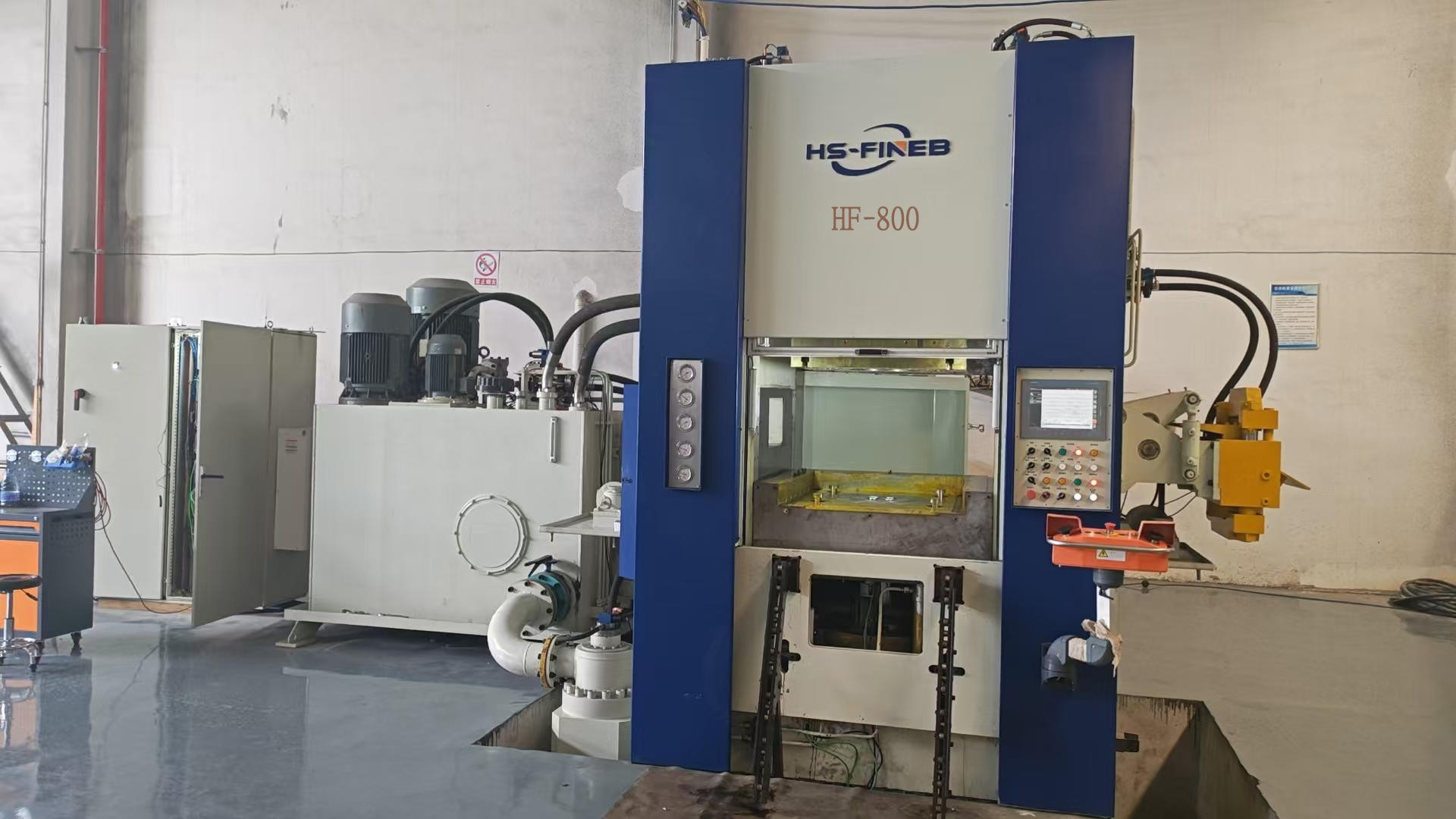
The combined weight of the press, die, coil feeding equipment, and hydraulic oil must not exceed the floor's rated loading capacity. For reference: HF-320 press weight is approximately 18 tons; HF-500 is approximately 35 tons; HF-800 is approximately 60 tons; HF-1200 is approximately 98 tons. Add die weight (typically 2-15 tons depending on part size and complexity), coil feeding equipment (2-5 tons), and hydraulic oil volume (200-800 liters at 0.9 kg/liter). The floor loading specification must account for this total, expressed as point loads at the press mounting points rather than uniformly distributed load, because the press transmits force through specific anchor bolt locations, not across the entire footprint.
Fine blanking press operation generates two vibration modes: high-frequency vibration from the blanking impact (transmitted through the frame to the foundation) and low-frequency vibration from the hydraulic system pulsation. For presses on ground-floor industrial floors with no adjacent sensitive equipment, standard foundation isolation is typically adequate. For presses on elevated floors, in shared buildings, or near measurement laboratories, specify vibration isolators between the press base and foundation. The isolator specification depends on the press weight and the building's natural frequency — our engineering team provides the required isolator specification based on the installation conditions.

4. Electrical Supply: Fine blanking presses require three-phase power at the voltage and frequency of the destination country. Standard options include 380V/50Hz (China, Europe, most of Asia), 440V/60Hz (Japan, Korea, Taiwan), and 480V/60Hz (USA, Canada, Mexico). The main motor power scales with tonnage: HF-200 requires approximately 22 kW; HF-320 approximately 37 kW; HF-500 approximately 55 kW; HF-800 approximately 90 kW; HF-1200 approximately 132 kW. The electrical supply must include a dedicated circuit breaker, properly sized cable (accounting for starting current surge, which can reach 3-6 times rated current for hydraulic pump motors), and a ground connection meeting local electrical code requirements. A voltage stabilizer is recommended for facilities with unstable supply voltage.
5. Hydraulic Oil Supply & Disposal: The press requires hydraulic oil (ISO VG 46 or VG 68 mineral oil, depending on ambient temperature) filled to the tank capacity. Tank capacities range from approximately 200 liters (HF-200) to 800 liters (HF-1200). The buyer must procure oil locally — shipping oil internationally is impractical and many countries restrict oil import. Our documentation specifies the oil brand and grade equivalents for major suppliers (Shell, Mobil, BP, Total, Castrol). Oil disposal arrangements must comply with local environmental regulations — the buyer should establish a waste oil collection arrangement with a licensed disposal contractor before commissioning. Initial oil fill is performed by our field engineers during commissioning; the buyer provides the oil.
6. Compressed Air: Pneumatic systems on the press (die clamping, air blow-off for part ejection, pneumatic safety interlocks) require clean, dry compressed air at 6-8 bar pressure, with a flow rate of approximately 200-500 liters/minute depending on press size. The air supply must include a water separator and oil mist filter at the press connection point. Moisture in the compressed air causes corrosion in pneumatic valves and cylinders — a refrigerated air dryer is recommended for installations in humid climates.
Die handling is the most frequent heavy-lift operation on a fine blanking press. Die weights range from 2 tons (small connector dies) to 15+ tons (large transmission gear dies). The overhead crane must have capacity exceeding the heaviest die the facility will handle, with a minimum 5-ton crane recommended for 200T-400T presses and 15-20 ton crane for 800T-1200T presses. The crane hook must reach the press centerline with sufficient height to clear the press crown — typically 4-6 meters above floor level depending on press model. Jib cranes or gantry cranes are alternatives where overhead crane installation is impractical.
The press height — from floor to the top of the crown — varies by model: HF-200 is approximately 3.5 meters; HF-500 is approximately 4.5 meters; HF-800 is approximately 5.5 meters; HF-1200 is approximately 6.5 meters. Add clearance for crane hook travel (minimum 1 meter above the press crown for die lifting) and overhead utility routing (electrical cable trays, pneumatic lines). The minimum ceiling height for a 500T press installation is approximately 6 meters; for a 1200T press, approximately 8 meters. Verify ceiling height before ordering — a press that does not fit the building is a costly mistake.
Fine blanking press hydraulic systems operate optimally at oil temperatures of 35-50 degrees C and ambient temperatures of 15-35 degrees C. Facilities in cold-climate regions need facility heating to maintain minimum ambient temperature (hydraulic oil viscosity at low temperature causes pump cavitation and valve response delays). Facilities in tropical regions need enhanced oil cooling capacity. Humidity control (below 70% relative humidity) prevents condensation in electrical cabinets and hydraulic tanks. Process accuracy — particularly ram positioning repeatability — is affected by thermal expansion of the frame; facilities with large temperature swings may need to allow thermal stabilization time before critical production runs.
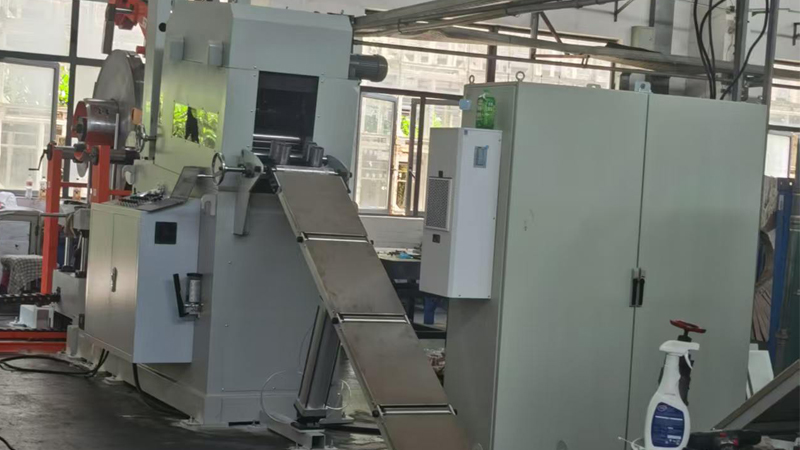
The production cell extends beyond the press footprint. Coil feeding requires space for a decoiler (2-3 meters behind the press), a leveler/straightener (1-2 meters), and strip feed mechanism. Coil storage area for incoming material and scrap handling space for skeleton waste (the remaining strip after parts are blanked) must be allocated. A 500T press cell typically requires 8 x 12 meters total floor area including the press, feeding equipment, die staging area, and part collection. For progressive die applications, add space for scrap conveyor discharge and part collection bins.

The following summary provides indicative site requirements by press model. These are planning values — the exact specification for your configuration is in the technical documentation package.
HF-200 (200T): Foundation: ~20 m², 400 mm depth. Press weight: ~12 tons. Main motor: ~22 kW. Oil capacity: ~200 liters. Min ceiling: ~5 m. Crane: 5-ton min. Total cell area: ~6 x 8 m.
HF-320 (320T): Foundation: ~25 m², 500 mm depth. Press weight: ~18 tons. Main motor: ~37 kW. Oil capacity: ~300 liters. Min ceiling: ~5.5 m. Crane: 5-ton min. Total cell area: ~6 x 9 m.
HF-500 (500T): Foundation: ~35 m², 600 mm depth. Press weight: ~35 tons. Main motor: ~55 kW. Oil capacity: ~400 liters. Min ceiling: ~6 m. Crane: 10-ton min. Total cell area: ~8 x 12 m.
HF-800 (800T): Foundation: ~45 m², 800 mm depth. Press weight: ~60 tons. Main motor: ~90 kW. Oil capacity: ~600 liters. Min ceiling: ~7 m. Crane: 15-ton min. Total cell area: ~9 x 14 m.
HF-1200 (1200T): Foundation: ~60 m², 1000 mm depth. Press weight: ~98 tons. Main motor: ~132 kW. Oil capacity: ~800 liters. Min ceiling: ~8 m. Crane: 20-ton min. Total cell area: ~10 x 16 m.
Foundation rebar specifications, anchor bolt patterns, and utility connection points are provided in the site preparation drawing issued with each order. The buyer's civil engineering contractor should use this drawing for foundation construction. We recommend the buyer engage a local structural engineer to review the foundation design against local soil conditions and building code requirements.
Contact Helen today for a detailed quotation, technical consultation, or factory tour arrangement. Our engineering team responds within 24 hours.