💬 WhatsApp Chat

Fine Blanking for Transmission Gears

Planetary, helical, and spur gears fine-blanked to AGMA Q8-9 — tooth flanks with 100% shear zone, eliminating hobbing for teeth under module 3.

Gear Quality Revolution

A Fine-Blanked Gear Tooth Under Module 3 Needs No Hobbing — the Die Cuts the Involute Profile

For decades, the production of transmission gears followed a fixed sequence: blank the gear profile from plate or coil, then hob the involute teeth on a dedicated gear cutting machine. The hobbing step added 15-40 seconds of cycle time per gear, required separate tooling and machine investment, and left tool marks on the tooth flanks that required subsequent shaving or grinding to meet automotive noise specifications. Fine blanking changes this paradigm for gears below module 3.

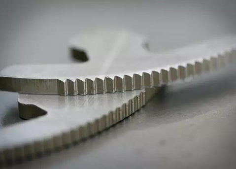
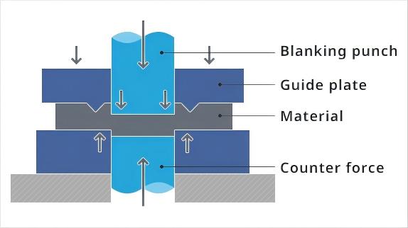
When the carbide die cavity contains the complete involute tooth profile — ground by wire-EDM to ±0.005 mm accuracy — the V-ring compresses material into each tooth cavity during the blanking stroke. The counter-pressure holds the gear blank flat against the punch face, preventing the material relaxation that distorts tooth geometry. The result is a gear with 100% shear zone on both tooth flanks, the tooth root fillet and the tooth tip, at AGMA Q8-9 quality level — two to three quality grades above conventional stamping, which typically achieves only Q5-6 due to the fracture zone on the tooth profile.

For automotive transmissions where gears operate at module 1.5-2.5, this means the gear comes off the press ready for heat treatment — no hobbing, no shaving, no grinding. The HF-500, HF-800 and HF-1200 presses cover the full range of transmission gear production, from 500-ton spur gears to 1200-ton planetary carriers.

Fine-blanked transmission gear with 100% shear tooth flanks
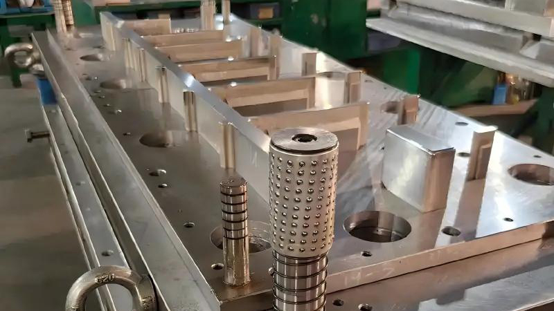
Fine blanking die with involute tooth profile for transmission gears
Single-Stroke Tooth Generation

Gear Tooth Formation: Involute Die Profile in a Single Stroke

The physics of fine-blanked gear teeth differ fundamentally from hobbed teeth. Hobbing removes material by cutting — the hob cutter traverses the gear blank, generating the involute profile through a series of envelope cuts that leave scallop marks on the tooth flank. Fine blanking forms the tooth by shearing — the die cavity determines the final geometry, and the material flows into the cavity under triaxial compression, producing a fully burnished tooth flank with surface finish below 1.6 µm Ra.

The involute profile is ground into the carbide die plate using wire-EDM with a 0.1 mm brass wire at five passes of decreasing spark energy. The final pass achieves ±0.005 mm profile accuracy and a surface finish of 0.4 µm Ra on the die cavity wall. This accuracy transfers directly to the gear tooth: the 100% shear zone replicates the die cavity geometry without the deformation, fracture or rollover that characterizes conventionally stamped gears.

The V-ring geometry surrounding each tooth cavity is critical. For module 2.0 teeth in 5 mm thick 16MnCr5, the V-ring distance from the tooth profile is 1.5-2.0 mm, V-ring depth is 0.4-0.6 mm, and the V-ring angle is 45°. This configuration ensures that material flows into the tooth cavity rather than laterally, maintaining full shear zone depth on both the pressure and clearance tooth flanks.

Simultaneous Multi-Tooth

Planetary Gear Carriers: Multi-Tooth Simultaneous Blanking

Planetary gear sets — the core of modern automatic and hybrid transmissions — use a carrier that holds three to six planet gears on pins. The carrier plate itself is a fine-blanked component with multiple precision holes for the gear pins, and the planet gears are fine-blanked from 16MnCr5 at module 1.5-2.5. The critical advantage of fine blanking for planetary gears is the simultaneous formation of all teeth in a single stroke — the die contains the complete gear circumference, so tooth-to-tooth pitch variation is determined by the die cavity accuracy, not by feed positioning error.

For planetary carrier plates, the pin hole positional accuracy determines gear mesh alignment. Fine blanking produces all pin holes in a single stroke with positional tolerance of ±0.02 mm relative to the carrier OD — achievable because the die cavity for all holes is ground from a single carbide plate, maintaining the inter-hole relationship to wire-EDM accuracy. Conventional drilling of pin holes accumulates positioning error across the hole pattern, requiring subsequent reaming or boring to achieve the mesh alignment tolerance.

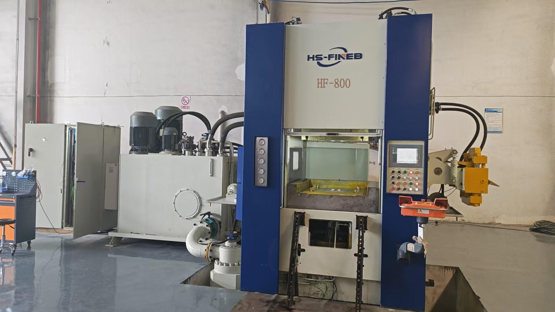
Planetary gear production typically requires 500-800 tons of blanking force depending on gear PCD (pitch circle diameter) and tooth count. The HF-800 with 8000 kN total pressure and 800×800 mm working table handles planetary carriers up to 300 mm PCD, while the HF-500 covers smaller planetary sets up to 200 mm PCD.

Fine blanking process for planetary gear carrier production
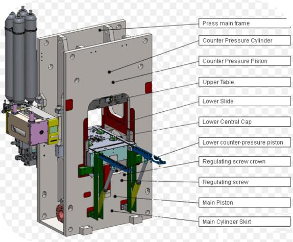
Fine blanking machine structure for helical gear production
Angled V-Ring Technology

Helical Gear Fine Blanking: Angled V-Ring and Specialized Die

Helical gears — used in dual-clutch transmissions and final drive reductions — present a unique fine blanking challenge: the tooth profile is not perpendicular to the gear face but helically angled at 15-30°. This means the cutting direction must accommodate a tooth that extends across the material thickness at an angle, requiring the die cavity to be machined with the helical lead built into the tooth profile.

HS-FINEB engineers helical gear dies with an angled V-ring that follows the helix angle, ensuring that material compression occurs along the full helical tooth length rather than only at the gear face. The counter-pressure pad is machined with a matching helical relief to prevent material distortion during the cutting stroke. The result is a helical gear with 100% shear zone on both tooth flanks along the full helix length — something conventional stamping cannot achieve because the angled tooth geometry causes asymmetric material flow that triggers edge fracture on the trailing flank.

Helical gear fine blanking requires 20-30% additional force compared to spur gears of the same module and PCD, due to the increased cutting perimeter and the angled V-ring resistance. For module 2.0 helical gears at 5 mm thickness, typical force requirements are 800-1200 tons. The HF-1200 with 12,000 kN total force is the production platform for large-diameter helical gears in heavy-duty transmission applications.

Material Selection

Case-Hardening Steel Grades for Gear Fine Blanking

16MnCr5

The industry-standard case-hardening steel for transmission gears. Carburized at 850-880°C to a case depth of 0.5-1.0 mm, achieving 58-62 HRC surface hardness with a tough 300-350 HB core. Fine blanking in the soft-annealed condition (180-220 HB) produces 100% shear zone on the tooth profile; the carburizing treatment after blanking hardens the already work-hardened shear zone to 65-68 HRC.

20MnCr5

Higher-carbon variant for gears with increased load capacity. Case depth 0.8-1.5 mm, surface hardness 60-64 HRC. The slightly higher carbon content (0.20% vs 0.16%) requires 5-10% additional blanking force but provides greater wear resistance on the tooth flanks after heat treatment. Fine blanking response is similar to 16MnCr5, with die-roll below 12% of material thickness.

Case-Hardening Grades

Additional grades include 18CrMo4, 21NiCrMo5 and SAE 8620 for specialized transmission applications. Each grade has specific V-ring depth, counter-pressure and blanking speed requirements. Our engineers configure the press parameters per material grade during the quoting process to ensure 100% shear zone on the involute tooth profile.

View full material processing guide →

Quality & Tooling Data

AGMA Quality Levels and Die Life for Fine-Blanked Gears

Gear TypeModule RangeAGMA QualityTypical ForceDie Life (strokes)
Spur gear (fine-blanked)0.5-3.0Q8-9500-800T150,000-300,000
Spur gear (conventional stamp)0.5-3.0Q5-6300-500T100,000-200,000
Planetary gear1.5-2.5Q8-9500-800T150,000-250,000
Helical gear1.5-2.5Q8800-1200T100,000-200,000
Planetary carrier plateN/A (pin holes)Q8 (positional)500-1200T200,000-300,000
Note: AGMA quality levels are measured per AGMA 2000-A88. Die life figures assume tungsten carbide die inserts (K20-K30 grade), 0.5% material thickness clearance, and per-material blanking speed programming. Gears above module 3.0 require hobbing after fine blanking — the fine blanking produces the gear blank profile and pierces the center hole, while the teeth are hobbed to final geometry. Contact our engineers for project-specific force and quality calculations.
Recommended Presses

HS-FINEB Models for Transmission Gear Production

HF-500HF-500 fine blanking press for spur gear production

HF-500 (500T)

Entry platform for spur gears at module 1.5-2.0. 5000 kN total force, 2500 kN V-ring, 1250 kN counter-pressure. Carbide die life 200,000+ strokes for 16MnCr5 gears.

HF-800HF-800 fine blanking press for planetary gears

HF-800 (800T)

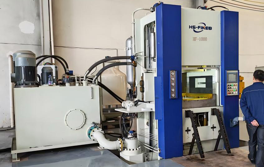
Production standard for planetary gears and carriers at module 2.0-2.5. 8000 kN total force, 800×800 mm table for large-PCD gear dies.

HF-1200HF-1200 fine blanking press for helical gears

HF-1200 (1200T)

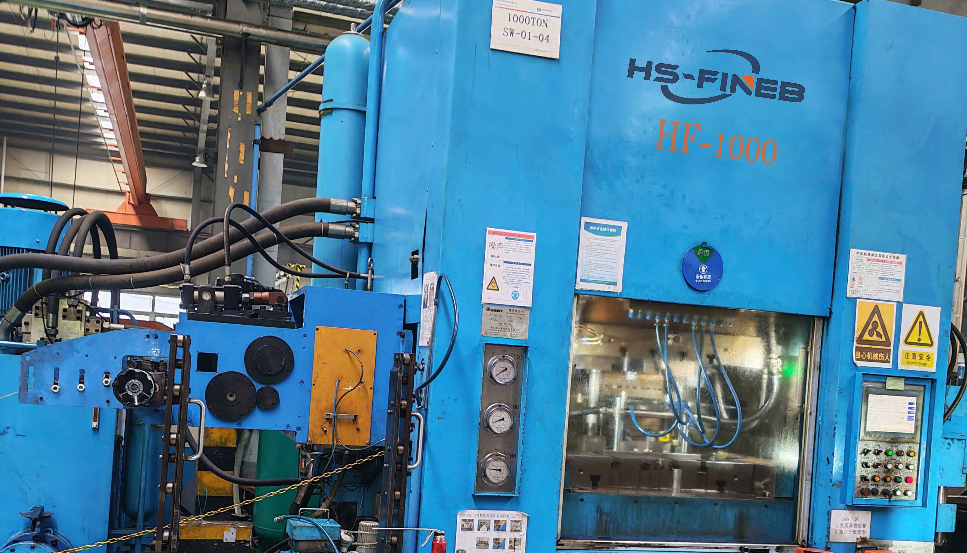
High-force platform for helical gears and large planetary carriers. 12,000 kN total force handles angled V-ring resistance on helical tooth profiles.

Die Engineering

Wire-EDM Carbide Tooth Profiles for Gear Dies

The involute tooth profile in the die cavity is the single most critical dimension in gear fine blanking. HS-FINEB uses five-pass wire-EDM with 0.1 mm brass wire to cut the carbide die cavity, with the final pass achieving ±0.005 mm profile accuracy and 0.4 µm Ra surface finish. The die cavity is then polished in the tooth root and flank areas to reduce friction during material flow, extending die life by 20-30% compared to unpolished cavities.

The V-ring insert is a separate carbide component surrounding the gear tooth cavity, allowing independent replacement when V-ring wear affects material compression. This modular die design reduces tooling cost per stroke by 40% compared to monolithic dies, where V-ring wear requires complete die plate replacement. Learn about our die design process →

Wire-EDM carbide die cavity for fine blanking transmission gears

Have a Transmission Gear to Evaluate for Fine Blanking?

Send your gear drawing with module, PCD, tooth count and material grade. Our engineers will assess fine blanking feasibility, calculate the involute die cavity requirements, and recommend the right HF-series platform for your gear production — with or without post-blanking hobbing.

💬