💬 WhatsApp Chat

Complex Fine Blanked Part Solutions

Some parts do not fit neatly into a standard part-family description — multiple thicknesses, combined forming and blanking, tight assembly-fit tolerances, or geometry that pushes die design past the routine case. Here is how we approach the genuinely complex ones, with engineering rigor rather than guesswork.

Engineering Challenge

What Makes a Part “Complex” for Fine Blanking

A part becomes complex for fine blanking when it combines two or more of these characteristics: multiple features that cannot all be produced in a single station, tolerances that push against the limits of what the process can hold, materials that challenge die life economics, or geometries that require combining forming operations with blanking in the same tooling system.

Complexity is not about part size or volume — a 20 mm washer with a single bore is routine, regardless of whether you need 100 or 1,000,000 pieces. A 60 mm seat recliner plate with formed gear teeth, a cam profile, coined rivet holes, and four mounting holes that must hold ±0.02 mm true position to each other is complex, even at modest volume. The complexity lives in the interaction between features, not in any single feature itself.

The five categories we regularly solve for are: blanking combined with forming, multi-thickness or stepped geometry, high feature density with tight web widths, tight assembly-fit tolerances across mating parts, and non-standard or difficult materials. Each category requires specific die design strategies, and many complex parts span two or three categories simultaneously.

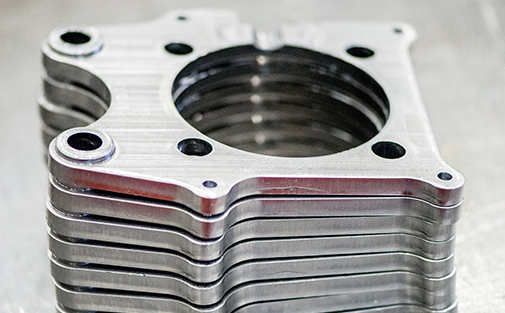
Complex fine blanked parts including multi-feature seat recliner mechanisms, gear carriers, and connector strips with combined forming and blanking
Design Rules

Design for Fine Blanking: Engineering Constraints

Complex parts are feasible only when their geometry respects the physical constraints of the fine blanking process. These are the design rules that determine whether a complex part can be fine blanked as drawn, or whether geometry modifications are needed.

Design ParameterMinimum ValueEngineering Rationale
Wall thickness (web between features)1.0 × material thickness (t)Thinner webs risk die plate cracking between adjacent punches and strip tearing in progressive dies
Hole-to-edge distance1.5 × t (minimum 1.5 mm)Ensures sufficient die body material around the stinger aperture to resist cracking under repeated loading
Hole-to-hole distance2.5 × stinger diameterMaintains die plate strength between adjacent internal feature punches; below this, guided stingers with support sleeves are required
Inner corner fillet radius0.3 × t (minimum 0.2 mm)Sharp inner corners concentrate stress on the die plate and initiate fatigue cracks; fillets distribute the stress
Outer corner radius0.2 × t (minimum 0.1 mm)Outer corners can be sharper than inner corners but still require a minimum radius to prevent punch edge chipping
Slot width1.0 × t (minimum 1.0 mm)Narrower slots require specialized stinger geometry and may need wire-EDM manufacture instead of conventional grinding
Formed feature height0.5 × t (max for single-stage forming)Deeper forms require multiple progressive stations or may exceed the fine blanking press’s forming capacity
Aspect ratio (largest/smallest feature)< 10:1Extreme aspect ratios create uneven force distribution across the die, requiring segmented punch design
Design review principle: If your part drawing violates any of these constraints, it does not necessarily mean fine blanking is impossible — but it does mean the part needs design review before tooling begins. We will identify which constraints are violated and propose specific geometry modifications that maintain functional intent while making the part manufacturable. See our die design overview for the broader design process.
Complexity Categories

Complexity Categories We Regularly Solve

These five categories cover the majority of complex fine blanking challenges we encounter and resolve for customers.

Blanking Combined with Forming

Parts requiring bends, coined steps, or partial-form features integrated into the same progressive die sequence as blanking operations. This keeps dimensional relationships between the blank and formed feature tighter than a two-process approach, at the cost of more complex die design and longer development timeline. Forming stations are placed before the final blanking station so formed features are held flat during the cutting stroke.

Multi-Thickness / Stepped Geometry

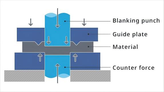
Parts with coined or partially-blanked features creating different effective thicknesses within the same part — common in connector and lock components where a functional step or shoulder is needed. This requires careful V-ring and counter-force tuning across varying geometry, since a single force profile optimized for the full-thickness section may not suit the thinner feature.

High Feature Density / Tight Web Widths

Parts where many features sit close together, leaving minimal material web between them. Strip strength through a progressive die sequence becomes the binding constraint — feature sequence and station layout must be engineered specifically to keep the strip from tearing as it advances. Idle stations are often required between dense feature stations for die body strength.

Tight Assembly-Fit Across Mating Parts

Multi-part assemblies where two or more fine blanked components must mate with tight positional tolerance to each other — not just to their own drawing. This sometimes means designing the dies for mating parts together, coordinating datum strategy across both, rather than treating each part’s tooling as an independent project.

Non-Standard or Difficult Materials

Higher-strength AHSS, work-hardening stainless, or abrasive copper alloys at production volumes that make die wear economics a first-order design consideration, not an afterthought. Material and tooling decisions interact here — the same part geometry in SUS304 vs C45 steel may require entirely different die material, coating, and clearance strategies.

Case Examples

Examples of Complex Fine Blanked Parts

These real-world examples illustrate how complex part challenges are resolved through integrated die design and engineering process.

Seat Recliner Mechanism

A single part combining formed gear teeth, a cam profile, coined rivet holes, and four mounting holes — all produced in one progressive die with 7 stations. The gear teeth are formed at station 4 (coined to full depth), the cam profile is partially cut at station 5, and the complete outer profile including teeth and cam is fine-blanked at station 6 with full V-ring engagement. See our seat recliner solution for the full case study.

Multi-Level Gear Carrier

A transmission gear carrier with two levels of coined features at different thicknesses, plus precision bolt holes that must hold true position to ±0.02 mm relative to the gear pitch circle. The die uses selective V-ring segments that engage only the full-thickness sections, with reduced counter-pressure on the coined areas to prevent deformation.

Lock Cylinder Cam

A security lock cam with an irregular outer profile, internal keyway slot, and a coined step for spring engagement. The tight web between the keyway and the outer profile (0.8 mm on 3 mm material) required a guided stinger with support sleeve and a segmented punch to prevent die plate cracking. Production runs at 35 strokes per minute with 500K+ die life.

Automotive Connector Strip

A 12-contact electronic connector strip in 0.4 mm phosphor bronze with 24 precision slots, a formed contact beam, and a parting line — all within a 25 mm × 8 mm part. The progressive die uses 10 stations with specialized thin-gauge V-ring geometry. Material utilization reaches 72% through interlocked double-row nesting.

Engineering Process

Engineering Support Process & Prototyping

Complex parts require a structured engineering process that validates feasibility before tooling investment. Our process begins with a part drawing and target volume — the same starting point as any project — but the review that follows is fundamentally different for complex parts.

Step 1 — Feasibility Review: We analyze the part drawing against the design for fine blanking constraints, identifying any violations and categorizing the complexity type. This review takes 3–5 business days and results in a written feasibility assessment with specific recommendations.

Step 2 — Geometry Optimization: If the part as drawn violates fine blanking constraints, we propose specific geometry modifications that maintain functional intent while making the part manufacturable. This is a collaborative process — we explain why each modification is needed and what the alternative would cost in terms of die complexity or process steps.

Step 3 — Prototyping: For genuinely complex geometries, we produce prototype parts using soft tooling (unhardened die steel) or wire-EDM cut samples to validate edge quality, flatness, and dimensional accuracy before committing to production tooling. This adds 2–4 weeks to the timeline but eliminates the risk of discovering feasibility problems after a €40,000+ production die is built.

Step 4 — Production Die Design & Build: Only after prototype validation do we proceed to production die design. The die is built, commissioned, and first-article inspected to the part drawing — with PPAP documentation available for automotive programs. Learn more about our fine blanking technology and die design process.

Complex fine blanked part prototyping process showing feasibility review, geometry optimization, and prototype validation

Bring Us Your Hardest Part

If a part has been difficult to source, or a previous supplier has told you it “cannot be fine blanked,” it is often worth a second opinion. Send us the drawing and we will give you a direct, engineering-led answer — including specific geometry modifications if the part needs them, and a clear explanation of why if it genuinely cannot be fine blanked as designed.

💬