Why fine blanking produces parts that conventional stamping cannot — the triple-action hydraulic principle, V-ring impingement, and counter-pressure explained from first principles.
Conventional stamping drives a punch through sheet metal in a single downward stroke. The material fractures unpredictably — you get a ragged edge with 30–70% smooth shear and the remainder as rough fracture zone. For a bracket hidden inside a washing machine, that is acceptable. For a seatbelt anchor, a transmission gear, or a brake caliper plate, it is not.
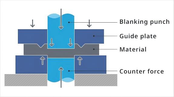
Fine blanking solves this by applying three independent hydraulic forces simultaneously during the cutting stroke. The blanking force shears the material, the V-ring force clamps the sheet flat around the die opening to prevent lateral material flow, and the counter-pressure holds the slug from below to keep it flat and suppress die-roll. The result: a clean, fully work-hardened shear edge with 100% smooth-cut surface, tolerances of IT7–8, and flatness under 0.05 mm — with zero secondary machining.
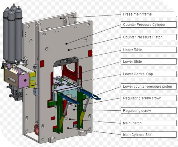
This triple-action principle is why a fine blanking press is not simply a heavier stamping press. It is a fundamentally different machine architecture with three independently controlled hydraulic circuits, each programmable as a percentage of total force. The press frame, guidance system, and hydraulic control must all be designed for this synchronized force application.
Each of the three hydraulic forces serves a distinct engineering purpose. Remove any one, and the edge quality collapses.
The main cutting force that drives the punch through the material. Its magnitude equals the material's shear strength multiplied by the cutting perimeter and sheet thickness. For a C45 steel gear blank of 4 mm thickness with a 120 mm OD, the blanking force alone may reach 180–220 tons. The press must deliver this force with minimal frame deflection — typically less than 0.05 mm per meter of bed width — to maintain uniform cutting clearance across the entire die.
A serrated ring descends onto the sheet metal around the die opening, impinging the material to prevent lateral flow during shearing. This is the single most important distinction from conventional stamping. Without the V-ring, material flows laterally ahead of the punch, initiating fracture rather than clean shear. The V-ring force typically runs at 20–50% of the blanking force, calibrated to material thickness and tensile strength. Double-ring configurations (V-rings on both plate and die) are used for materials above 5 mm.
Force applied from below the slug by a counter-piston, holding the part flat during the cutting stroke. This prevents die-roll — the rounded deformation at the cut edge — and maintains dimensional flatness. Counter-pressure is critical for thin parts below 2 mm and for high-strength materials where the slug tends to bow. Typical counter-pressure values range from 10–25% of the blanking force, adjusted upward for harder alloys and larger part geometries.
The difference is not incremental. It is the difference between a part that needs four secondary operations and one that needs none.
| Characteristic | Fine Blanking | Conventional Stamping |
|---|---|---|
| Edge Quality | 100% smooth shear surface | 30–70% shear + fracture zone |
| Tolerance | IT7–8 (±0.01–0.02 mm) | IT11–13 (±0.1 mm) |
| Flatness | <0.05 mm | >0.2 mm |
| Secondary Operations | None — burr-free, ready to use | Milling, drilling, deburring required |
| Die Life | 300K–1M hits per regrind | 100K–300K hits |
| Material Utilization | 60–75% | 40–60% |
| Surface Finish (Ra) | <0.4 μm on shear edge | 3–12 μm (fracture surface) |
| Tooling Cost | Higher (V-ring die, triple-action) | Lower (single-action die) |
A complete fine blanking cycle executes six precisely timed steps in a single press stroke. The entire sequence takes 0.5–3 seconds depending on material thickness and press tonnage, with cycle rates of 15–60 strokes per minute for parts up to 4 mm thick.
The critical phase is step 4 — the blanking stroke. Unlike conventional stamping, where the punch descends at maximum speed, fine blanking controls the cutting speed hydraulically. This controlled-speed shearing is what prevents adiabatic softening at the cutting edge and eliminates the micro-cracks that initiate fracture in conventional stamping.
Fine blanking is not always the right answer. These six scenarios define where it wins decisively over conventional stamping or machining.
When your drawing specifies a minimum smooth-cut surface of 80% or more on functional edges — sealing surfaces, bearing seats, or sliding contacts — only fine blanking can deliver this consistently without secondary finishing.
Thin parts that must remain perfectly flat after blanking — valve plates, clutch disks, shim washers — depend on counter-pressure to suppress warpage. Conventional stamping cannot hold flatness below 0.2 mm.
If your part currently goes from stamping to milling, drilling, and deburring, fine blanking may collapse three operations into one. The break-even point is often reached at volumes above 10,000 parts per month.
Fine blanking dies cost 2–3x more than conventional dies due to V-ring geometry and tighter clearances. At monthly volumes above 10K parts, the eliminated secondary operations and longer die life (300K–1M hits) deliver lower per-part cost.
Safety-critical components — seatbelt anchors, brake caliper pistons, steering yokes — require predictable, fully-work-hardened shear edges with no fracture-initiated micro-cracks. Fine blanking produces near-net-shape parts with metallurgically sound edges.
When the drawing calls out a surface roughness below 0.4 μm on functional edges — common for hydraulic valve plates and precision gears — the fine blanked shear edge delivers this directly off the press, no grinding required.
Send us your part drawing. We will evaluate whether fine blanking is the right process for your geometry, material, and volume — and recommend the press, die, and feed line to match.