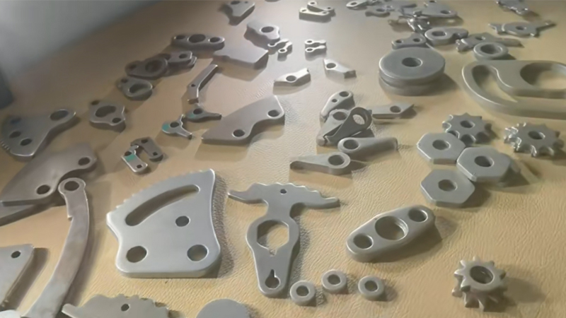
Exhaust flanges, heat shields, turbocharger components, and EGR valve plates combine two demands that do not naturally coexist: complex contour geometry in heat-resistant alloys that are significantly tougher on tooling than standard carbon steel. Fine blanking delivers leak-free sealing surfaces with no secondary machining — even in Inconel and ferritic stainless.
Thermal and exhaust components operate in environments where material temperatures reach 600–950°C. The materials specified for these applications — ferritic stainless steels, austenitic stainless, and nickel-based superalloys — are harder, more abrasive, and more prone to work-hardening than the carbon steels that dominate most fine blanking programs. This changes the die design, coating selection, and force parameters significantly.
SUS409 and SUS439 ferritic stainless steels are the workhorse materials for automotive exhaust systems. They offer good oxidation resistance at exhaust gas temperatures (600–800°C) and relatively moderate work-hardening behavior during shearing. Die life on SUS409 typically reaches 200K–350K hits per regrind with coated D2 tool steel dies — shorter than carbon steel but manageable for the production volumes involved.
For turbocharger and EGR components exposed to temperatures above 800°C, austenitic SUS304 and SUS316 are specified for their superior creep resistance. These materials work-harden aggressively during fine blanking, increasing surface hardness by 50–80 HV at the shear edge. This accelerates die wear by 40–60% compared to carbon steel, making tungsten carbide die inserts with TiAlN coating essential for programs exceeding 100K parts per month. See our materials guide for comprehensive fine blanking material data.
Material selection for thermal components directly determines die life, edge quality, and in-service performance. These are the materials we most commonly fine blank for exhaust and thermal applications.
| Material | Max Service Temp | Tensile Strength (MPa) | Fine Blanking Die Life | Typical Application |
|---|---|---|---|---|
| SUS409 | 750°C | 380–480 | 200K–350K hits | Exhaust flanges, hangers, heat shields |
| SUS439 | 850°C | 420–520 | 180K–300K hits | Catalytic converter shells, manifold flanges |
| SUS304 | 870°C | 520–750 | 120K–200K hits | EGR valve plates, turbo heat shields |
| SUS316 | 870°C | 520–680 | 130K–220K hits | Marine exhaust, chemical exhaust systems |
| Inconel 625 | 980°C | 830–1100 | 50K–100K hits | Turbocharger wastegate, high-temp flanges |
| RA330 | 1150°C | 600–750 | 80K–120K hits | Furnace components, extreme heat shields |
Fine blanking heat-resistant alloys requires die designs that account for the material’s different thermal and mechanical properties. Three engineering adjustments are critical.
Standard die clearance of 0.5% of material thickness, optimized for carbon steel, may be too tight for stainless and nickel alloys. Their higher work-hardening rate causes the material to resist shearing, increasing tonnage and edge cracking risk. For austenitic stainless, clearance is typically increased to 0.5–0.8% of t; for Inconel, 0.8–1.2% of t. This slightly relaxes edge quality but prevents die chipping and extends tool life.
Higher-strength alloys require greater V-ring force to prevent lateral material flow during shearing. For SUS304, V-ring force is set at 35–50% of blanking force (vs 20–30% for carbon steel). For Inconel 625, V-ring force may reach 50–60% of blanking force. This higher impingement is essential — without it, the harder material flows laterally ahead of the punch, initiating fracture instead of clean shear.
Heat-resistant alloys generate more heat at the cutting edge during shearing. If the cutting speed is too high, adiabatic heating softens the die edge, accelerating wear. Cutting speed for austenitic stainless is reduced to 5–8 mm/s (vs 8–15 mm/s for carbon steel); for Inconel, 3–5 mm/s. This reduces cycle rate but is essential for maintaining die edge integrity over production runs.
These are the part families where fine blanking consistently delivers value over conventional stamping or laser cutting for thermal and exhaust applications.
Exhaust manifold and catalytic converter flanges require perfectly flat sealing surfaces to maintain gasket integrity under thermal cycling. A warped flange face is a gasket leak waiting to happen. Fine blanking’s counter-pressure system holds flatness below 0.05 mm, and the 100% shear edge provides a ready-to-seal surface that mates directly with the gasket — no secondary surface milling required.
Multi-hole, complex-contour heat shields protect sensitive components from radiant exhaust heat. Their geometry — numerous mounting holes, complex outer profiles, and formed stiffening ribs — makes them natural candidates for progressive fine blanking dies. Material is typically SUS409 or SUS439 at 0.8–1.5 mm thickness, running at 40–60 strokes per minute.
Wastegate linkages, compressor housing brackets, and turbo heat shields operate at temperatures up to 950°C. Fine blanked components in Inconel 625 or SUS304 provide the high-temperature edge integrity and dimensional stability that turbocharger applications demand, with the work-hardened shear edge offering natural scaling resistance.
Exhaust gas recirculation valve plates control exhaust gas flow back to the intake. The plate edge must seal against the valve seat without leakage at temperatures of 600–750°C. Fine blanking produces the valve plate with 100% shear edge and flatness below 0.03 mm, ensuring consistent sealing performance across the valve’s duty cycle.
The case for fine blanking in exhaust and thermal applications rests on three engineering advantages that conventional processes cannot match.
The 100% shear edge produces a surface with Ra below 0.4 μm — smooth enough to seal directly against a gasket without secondary machining. Exhaust flanges produced by conventional stamping have rough fracture surfaces that require surface milling before they can seal reliably. Fine blanking eliminates this step entirely.
The work-hardened shear edge on fine blanked stainless and nickel alloy components reaches 250–400 HV — significantly harder than the base material. This hardened edge resists high-temperature erosion, oxidation, and scaling better than a machined edge, extending component service life in exhaust environments.
Conventional exhaust flange production involves stamping + CNC milling + drilling — three operations. Fine blanking produces the finished flange in a single stroke, with all holes pierced and the sealing surface ready. At automotive exhaust system volumes (50K–200K per month), this eliminates a significant production bottleneck.
Learn more about fine blanking technology, explore material specifications, or see our automotive braking components for another critical automotive application of fine blanking.
Send us your part drawing, material grade, and any sealing-face flatness callout. We will evaluate the fine blanking feasibility for your heat-resistant alloy, recommend die material and coating selections, and provide a transparent per-part cost comparison against laser cutting or conventional stamping plus machining.