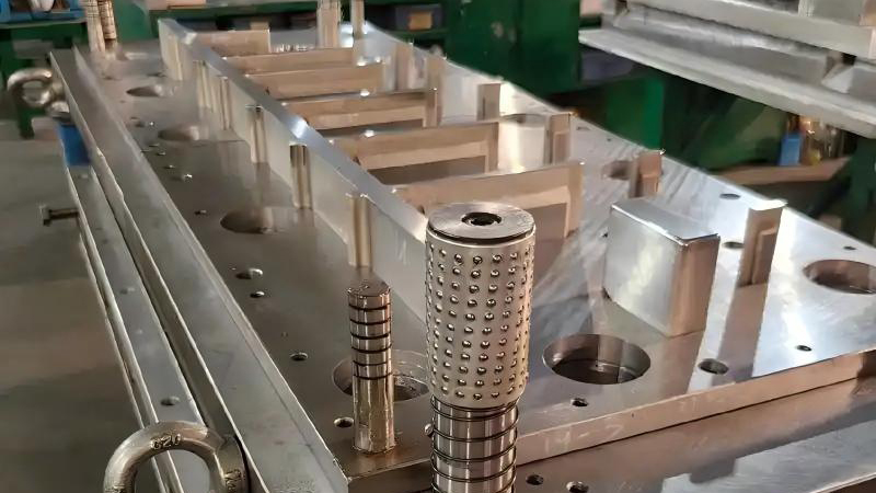
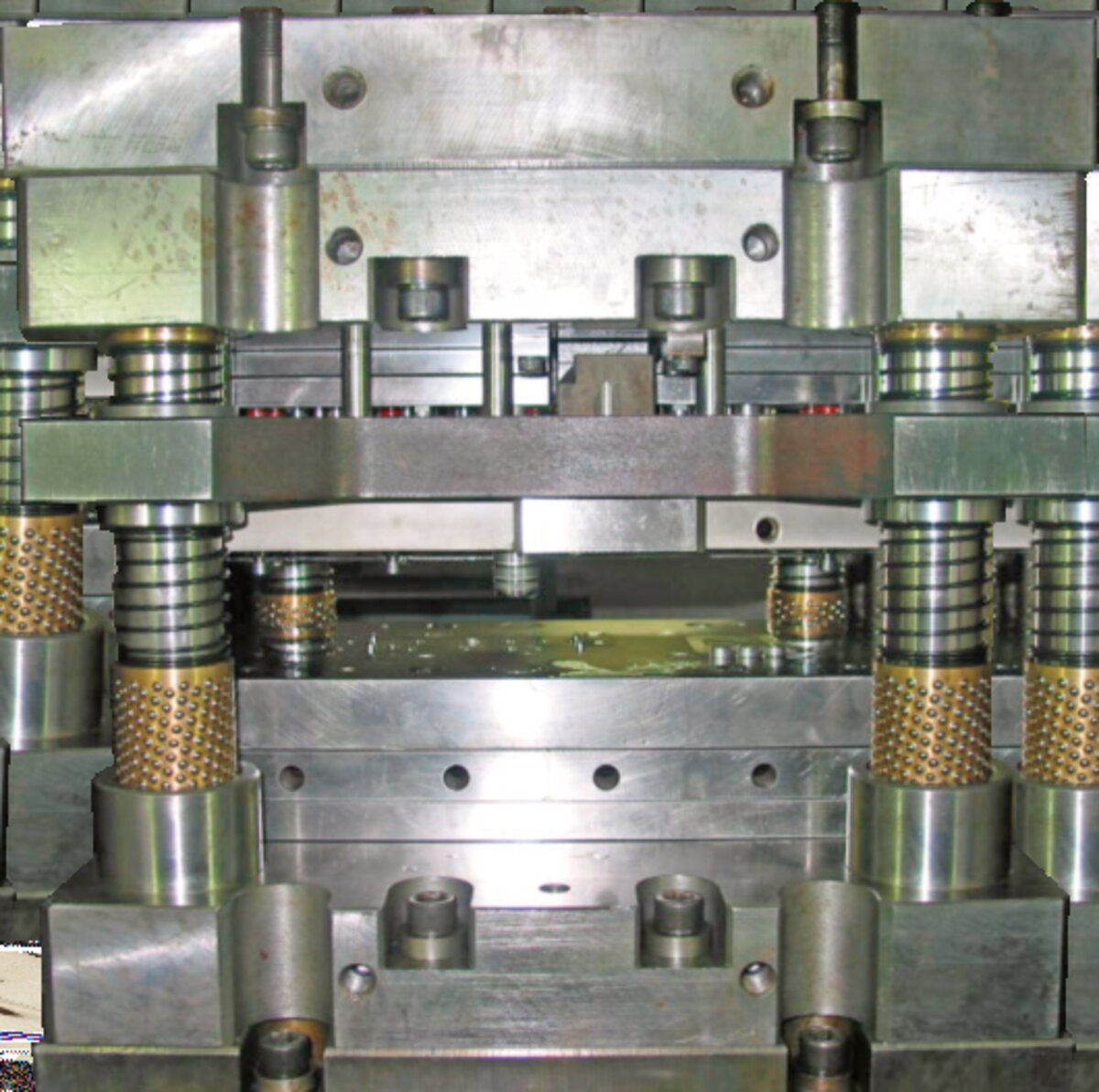
Where a progressive die spreads work across multiple stations, a compound die completes every feature — outer profile and all internal holes — in a single stroke at one station. Simpler to build, faster to commission, and often the more economical choice for parts with straightforward geometry and high precision requirements.
A compound fine blanking die is a single-station tooling system where the punch, die plate, V-ring plate, and counter-piston all act simultaneously in one press stroke. The outer profile is blanked downward through the die plate while internal features — holes, slots, windows — are pierced upward by stingers mounted in the die plate. The result: a fully finished part, complete with 100% shear edges on all cutting surfaces, drops off the press in a single stroke.
This architecture is fundamentally different from a progressive die, where features are distributed across stations and the part accumulates geometry as the strip advances. In a compound die, there is no strip advance, no pilot hole registration, and no cumulative feed error. Every feature is produced from the same die reference in the same stroke, which means hole-to-edge and hole-to-hole tolerances are held by die precision alone — not by feed accuracy.
The trade-off is tonnage. Because all cutting happens simultaneously, the peak tonnage in a compound die stroke equals the sum of all cutting perimeters multiplied by material shear strength. A part that requires 80 tons on a progressive die (where the 80 tons is distributed across 4 stations) may require 200–250 tons on a compound die. This can push the part into a larger press class than initially expected — a factor buyers often miss when comparing quotes that assume different die architectures.
Compound die architecture is not always the right answer. These criteria define where it wins decisively over progressive tooling.
Parts with one or two features — a gear blank with a center bore, a washer with a single hole, a sealing plate with bolt holes — are ideal for compound tooling. The part geometry does not require sequential operations that a compound die cannot perform.
When positional tolerance between internal holes and the outer profile must be held to ±0.02 mm or tighter, compound tooling eliminates the cumulative feed error inherent in progressive dies. All features share the same die reference.
A compound die uses one station rather than 4–8, meaning fewer die plates, punches, and guide components. Tooling cost is typically 40–60% lower than an equivalent progressive die for the same part.
Single-station dies are simpler to design, manufacture, and debug. Time from drawing approval to first article is typically 6–10 weeks, compared to 12–18 weeks for a complex progressive die.
Parts requiring bends, coined steps, or forming operations combined with blanking cannot be produced in a pure compound die. These require progressive architecture with forming stations.
If the combined cutting perimeter of all features exceeds the press capacity, a compound die is impractical. Distributing the work across progressive stations reduces peak tonnage per stroke.
A compound fine blanking die comprises four primary force-application components, each with a distinct engineering function. Their relative positioning and force coordination determine part quality.
The main cutting punch descends through the material, shearing the outer profile. Its cutting edge is profiled to match the part’s outer contour with 0.5% clearance relative to material thickness. The punch is typically manufactured from D2 or D3 tool steel, heat-treated to 60–62 HRC, with a TiCN or DLC coating for extended die life. For parts above 4 mm thickness, the punch may be segmented to reduce grinding complexity.
The stationary lower die plate contains the cutting aperture matching the part’s outer profile. It also houses the stingers — upward-pointing punches that pierce internal features. The die plate is manufactured from the same tool steel as the punch, with the cutting aperture wire-cut to ±0.005 mm tolerance. Die plate thickness must be sufficient to resist deflection under full blanking force — typically 1.5–2.5× the material thickness being cut.
The V-ring plate descends onto the sheet metal around the die aperture, impinging the material with a serrated ring to prevent lateral flow during shearing. In a compound die, the V-ring surrounds the entire part profile in a single continuous ring. V-ring geometry — typically a 60° to 90° V with 0.5–1.2 mm tooth height depending on material thickness — is the single most critical dimension for achieving 100% shear.
The counter-piston rises from within the die plate, applying upward force to hold the slug flat during the cutting stroke. In a compound die, the counter-piston also ejects the finished part upward after the stroke completes. Counter-pressure is set at 10–25% of total blanking force, adjusted for material hardness and part geometry. For thin parts below 2 mm, higher counter-pressure is needed to prevent die-roll.
Stingers are the internal-feature punches in a compound die. Mounted in the die plate and pointing upward, they pierce holes, slots, and windows as the main punch shears the outer profile downward. Because stingers cut in the opposite direction from the main punch, they produce 100% shear edges on internal features — the same quality as the outer profile.
Stinger design involves three critical engineering decisions. First, stinger diameter must be sufficient to withstand the buckling force during piercing. A stinger below 2 mm diameter on material above 3 mm thick risks buckling; in such cases, a guided stinger with a support sleeve is required. Second, stinger clearance is typically 0.5–1.0% of material thickness, slightly looser than the outer profile clearance to reduce punch loading. Third, stinger ejection force must be calibrated to push the pierced slug clear of the die plate without distorting the finished part.
For parts with many small holes — a sealing plate with 8–12 bolt holes, for example — stinger layout becomes a die body strength problem. The die plate between adjacent stingers must maintain enough material to resist cracking under repeated loading. Minimum stinger-to-stinger spacing is typically 2.5× the stinger diameter, or 1.5× material thickness, whichever is greater.
Die clearance, tooling cost, and die life differ significantly between compound and progressive architectures for the same part. Understanding these trade-offs is essential for making the right tooling decision.
| Parameter | Compound Die | Progressive Die |
|---|---|---|
| Die Clearance (outer profile) | 0.5% of t | 0.5% of t (final station) |
| Die Clearance (internal) | 0.5–1.0% of t (stingers) | 1.0–2.0% of t (piercing stations) |
| Peak Tonnage per Stroke | High (all features simultaneously) | Low (distributed across stations) |
| Tooling Cost | 40–60% lower | Baseline (higher due to multi-station) |
| Build Time | 6–10 weeks | 12–18 weeks |
| Die Life (hits per regrind) | 300K–800K | 300K–1M (per station) |
| Hole-to-Edge Tolerance | ±0.01–0.02 mm (single die reference) | ±0.03–0.05 mm (cumulative feed error) |
| Material Utilization | 50–65% (single part per stroke) | 60–75% (optimized nesting) |
| Production Rate | 20–40 strokes/min | 25–60 strokes/min |
Compound dies excel on parts with simple outer profiles and internal features where precision, not feature count, is the driving requirement.
Spur gears, sector gears, and internal ring gears are natural compound die applications — the tooth profile is blanked in one stroke with 100% shear on every tooth flank. See our gear fine blanking solutions for detailed specifications.
Thrust washers, sealing washers, and spring washers with a single bore and tight flatness requirements are ideal for compound tooling. See our precision washers page for material and tolerance specifications.
Flat brackets with mounting holes and sealing plates with bolt patterns — parts where the outer profile and internal holes must hold tight positional relationship — benefit from the single-die-reference precision of compound tooling.
Electric motor laminations with complex internal slot profiles and tight stacking tolerances are produced on compound dies where the inner and outer profiles are cut simultaneously to guarantee concentricity.
Send your part drawing and target volume. The decision between compound and progressive tooling is usually clear once we can see the actual geometry and production requirement — we will give you a direct, engineering-led recommendation. See our die design overview for the broader design process.