💬 WhatsApp Chat

Fine Blanking vs Conventional Stamping: Which Process to Choose?

A parameter-by-parameter comparison of force architecture, edge quality, tolerance, cost and production rate — with clear guidance on when each process is the right choice.

Process Selection

Two Processes, Different Physics

The choice between fine blanking and conventional stamping is not a question of "better" and "worse" — it is a question of process physics matching application requirements. Fine blanking and conventional stamping apply fundamentally different force architectures to the material, producing fundamentally different edge qualities, tolerances and production economics. Understanding these differences is essential for making the right process selection for each part.

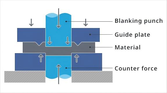
Fine blanking uses three simultaneous hydraulic forces — V-ring impingement, counter-pressure and blanking force — to constrain the material so tightly that it shears cleanly through 100% of its thickness. Conventional stamping uses a single ram force to push material through a die with relatively large clearance, causing the material to shear for one-third of its thickness then fracture (tear) for the remaining two-thirds. The result: fine blanking produces a smooth, accurate, burr-free edge; conventional stamping produces a rough, dimensionally inconsistent edge with a fracture zone and burr.

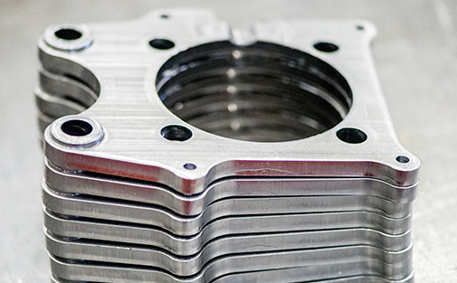
Fine-blanked precision metal part showing 100% smooth shear edge quality
Technical Comparison

Fine Blanking vs Conventional Stamping: Parameter by Parameter

ParameterFine BlankingConventional Stamping
Force architectureTriple force: V-ring + counter-pressure + blanking, applied simultaneously via 3 independent hydraulic circuitsSingle ram force; no V-ring, no counter-pressure
Tool clearance0.5% of material thickness (e.g., 0.025 mm for 5 mm material)5–10% of material thickness (e.g., 0.25–0.50 mm for 5 mm material)
Edge quality100% smooth shear zone; no fracture; no burr (die-roll < 15% of t)~30% shear zone + ~70% fracture/tear zone; burr present
Dimensional toleranceIT6–IT9 (typically ±0.01–0.05 mm)IT12–IT14 (typically ±0.1–0.5 mm)
Surface finish (edge)Ra ≤ 0.4 μmRa 1.6–6.3 μm (rough fracture surface)
FlatnessExcellent — counter-pressure prevents bulgingPoor — material bulges and distorts without counter-pressure
BurrMinimal, consistent; typically < 0.1 mmSignificant; requires deburring operation
Production rate30–60 SPM (strokes per minute)200–600 SPM
Tooling cost2–3× higher (V-ring, tight clearance, precision fit)Baseline (simpler die construction, looser clearance)
Press costHigher — triple-force hydraulic CNC pressLower — single-action mechanical or hydraulic press
Secondary operationsTypically none — net-shape partsOften required: deburring, machining, grinding, flattening
Material thickness range1–25 mm0.1–10 mm (thinner typical)
Force Architecture

Why the Edge Is Different

Fine blanking process diagram showing V-ring counter-pressure and blanking force triple-force architecture

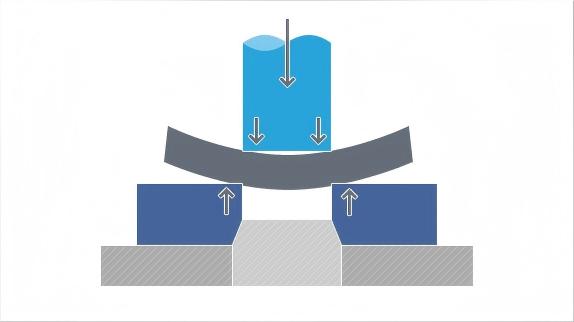
In conventional stamping, the punch descends with a single force and contacts the material. Because the die clearance is large (5–10% of material thickness), the material is free to deform laterally. As the punch penetrates, the material shears for approximately one-third of its thickness — this is the "shear zone" or "bright cut." At the one-third point, the accumulated stress exceeds the material's crack initiation threshold, and the remaining two-thirds fractures rapidly — this is the "fracture zone" or "tear." The fracture surface is rough, angled, dimensionally inconsistent and covered with burrs.

In fine blanking, the V-ring indents the material around the cutting line before the punch contacts, creating a physical constraining groove. The counter-pressure pushes upward from below, preventing downward bulging. The die clearance is extremely tight (0.5% of material thickness). Under these constrained conditions, the material cannot deform laterally or bulge — it has nowhere to go but to shear. The shear zone extends through 100% of the material thickness without transitioning to fracture. The result is a smooth, bright, dimensionally accurate edge with minimal die-roll (the rounded edge at the top of the cut, caused by V-ring indentation) and virtually no burr.

The counter-pressure force is critical: without it, even with the V-ring, the material would still bulge downward and crack. The V-ring prevents lateral flow; the counter-pressure prevents vertical flow. Together, they create the hydrostatic compressive stress state at the cutting line that suppresses crack initiation and forces clean shearing through the full thickness.

Selection Guidance

When to Choose Each Process

Choose Fine Blanking When:

  • Functional edges are required: The part edge is a working surface — a gear tooth, a sealing face, a sliding surface, a locating edge. The edge must be smooth, accurate and consistent.
  • No secondary machining is desired: The cost of milling, drilling, deburring or grinding after stamping exceeds the cost premium of fine blanking. This is typically the case at production volumes above 50,000 parts/year.
  • Tight tolerances are specified: The part drawing calls out IT6–IT9 tolerances, ±0.01–0.05 mm. Conventional stamping cannot reliably achieve these tolerances.
  • Flatness is critical: The part must be flat without a separate flattening operation — e.g., brake caliper bodies, valve plates, thrust washers.
  • High production volume: Annual volumes above 100,000 parts justify the higher tooling cost through amortization. At 500,000+ parts/year, fine blanking is almost always the lower cost-per-part option.
  • Material is ≤ 25 mm thick: Fine blanking is effective across 1–25 mm material thickness, covering most precision sheet metal applications.

Conventional Stamping Is Sufficient When:

  • Non-functional edges: The part edge is cosmetic or non-critical — it does not contact another part, does not seal, does not locate. The rough fracture edge is acceptable.
  • Lower volume: Annual volumes below 30,000 parts. The tooling cost premium for fine blanking is not amortized at low volume, and secondary machining may be more economical.
  • Looser tolerances are acceptable: The part drawing allows IT12–IT14 tolerances (±0.1–0.5 mm). Stamping can meet these reliably.
  • Secondary operations are already planned: The part requires machining or grinding anyway (e.g., holes to be drilled, surfaces to be milled), so edge quality from stamping is irrelevant.
  • High-speed production is the priority: The part is a high-volume commodity (e.g., simple brackets, washers, covers) where 200–600 SPM production rate outweighs edge quality.
  • Material is very thin (< 0.5 mm): Very thin materials are challenging for fine blanking V-ring geometry; conventional stamping may be more practical.
Cost Analysis

Cost-Per-Part: Tooling Amortization

Conventional stamping press for comparison with fine blanking process

The cost-per-part comparison must account for tooling, press, material, labor and secondary operations. Here is a simplified example for a mid-size automotive bracket (80 mm × 40 mm, 5 mm thick, C45 steel, annual volume 200,000 parts):

  • Fine blanking: Tooling cost ~$15,000 (progressive die with V-ring); press investment amortized at ~$0.05/part; no secondary operations; material ~$0.08/part; total ~$0.20/part at 200,000/year. Tool life: 300,000–500,000 parts before resharpening.
  • Conventional stamping + secondary: Tooling cost ~$6,000; press amortized at ~$0.02/part; secondary deburring/machining ~$0.15/part; material ~$0.08/part; total ~$0.31/part at 200,000/year. Tool life: 200,000–400,000 parts before resharpening.

At 200,000 parts/year, fine blanking saves $0.11/part — $22,000/year — despite higher tooling and press costs. The break-even volume (where fine blanking's higher tooling cost is offset by lower per-part cost) is typically 30,000–50,000 parts/year for parts requiring secondary machining after stamping. Below that volume, conventional stamping with secondary operations is usually cheaper; above it, fine blanking wins.

The calculation shifts with part complexity. For simple parts with non-functional edges, conventional stamping wins at any volume. For complex parts with functional edges (gears, calipers, mechanisms), fine blanking wins at volumes as low as 15,000–20,000 parts/year because the secondary machining cost to achieve equivalent edge quality would be prohibitive.

Hybrid Approach

When Both Processes Are Used Together

In practice, many manufacturing operations use both fine blanking and conventional stamping in the same production line — each process assigned to the parts where it delivers the best economic and quality balance. A typical automotive supplier might fine blank the functional edges on gear teeth and caliper interfaces while conventionally stamping the non-critical mounting tabs and cosmetic covers. The fine blanking press handles the parts demanding IT7–IT8 tolerance and 100% smooth shear edge; the conventional stamping press handles the parts where IT12–IT14 is sufficient and the production rate of 300+ SPM matters more than edge quality. This hybrid approach optimizes total cost across the part family — investing in fine blanking where it pays and using stamping where it is sufficient. The key engineering decision is process assignment: which parts go on which press, based on functional edge requirements, tolerance specifications and annual volume economics.

Not Sure Which Process Your Parts Need?

Send us your part drawings and annual volume. Our engineers will evaluate both fine blanking and conventional stamping feasibility and recommend the most cost-effective process for your application.

💬