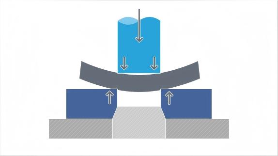
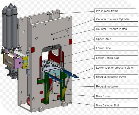
Nine platforms, one engineering philosophy. Tonnage is the starting point — but the real selection process runs backward from your part: shear perimeter x material shear strength x thickness = total blanking force. Add V-ring impingement and counter-pressure, and the right platform emerges from the math, not from a catalog page.

Choose the HF-200 when your part's total blanking force — shear perimeter x thickness x material shear strength — falls under 1800 kN with 8mm material ceiling. Typical fit: brass lock cylinders, phosphor-bronze connector terminals, low-carbon steel hardware under 50mm blanking diameter. The 80 SPM stroke rate suits high-volume, small-part production where die-roll tolerance is generous.

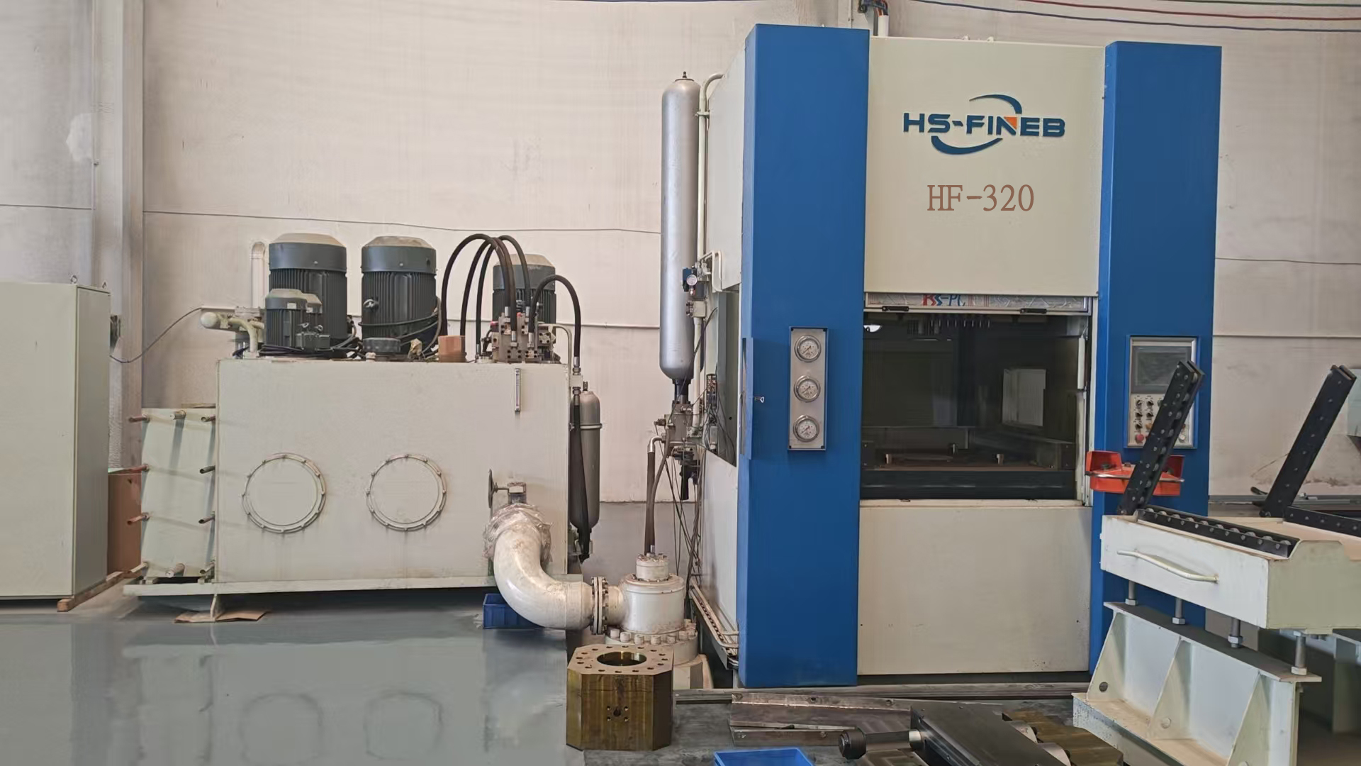
The decision point between entry-level and mid-range. Select the HF-320 when 16MnCr5 or C45 parts at 6-12mm thickness demand independently programmable V-ring force (1600 kN) and counter-pressure (800 kN) for die-roll control under 10% of material thickness. Ideal for seat-recliner gears and clutch plates where flatness within 0.05mm is a non-negotiable acceptance criterion.

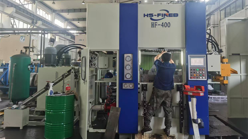
Step up to the HF-400 when part diameter exceeds 250mm or material thickness reaches 14mm in HSLA grades like S500MC. The 650x650mm working table accommodates dies with multiple V-ring stations, and 2000 kN ring-gear force prevents fracture-zone tearing on higher-strength alloys where a 320T platform would leave visible die-roll.

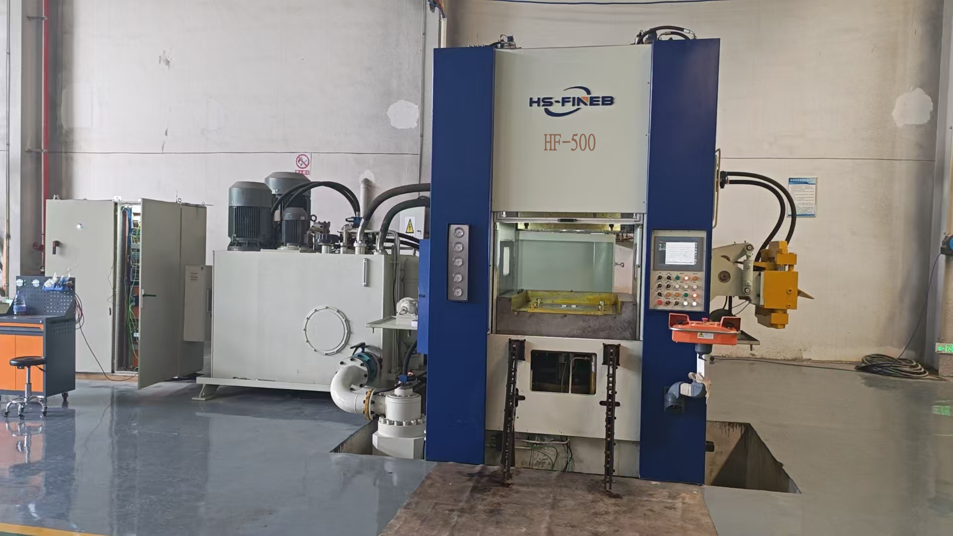
Select the HF-500 when migrating machined structural parts to fine blanking. At 15mm thickness in S500MC or 16MnCr5, the 2500 kN V-ring and 1250 kN counter-pressure produce shear edges that eliminate milling and grinding — delivering 40-60% per-part cost reduction on brake-caliper brackets and powertrain mounts at volumes above 50,000 units per year.

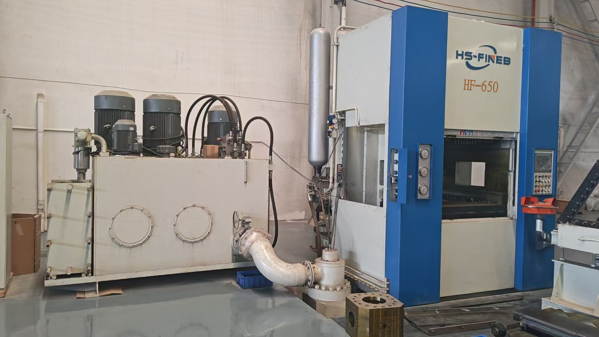
Choose the HF-650 when transmission ring gears exceed 200mm pitch diameter or thick-plate parts reach 16mm in 16MnCr5. The 3250 kN V-ring force maintains full material impingement on high-carbon steels where die-roll must stay below 0.3mm — the threshold below which gear teeth can mesh directly after blanking with no secondary hobbing or shaving.

The HF-700 is selected when a single stroke must produce a finished component from a multi-station progressive die — formed, pierced and blanked in one pass. The 900x900mm table and 3500 kN V-ring force support complex die stacks up to 18mm, making it the decision point for seat-track locking plates and seatbelt retractor gears.

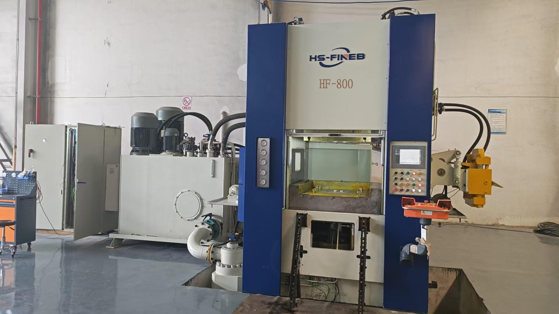
Step up to the HF-800 when truck chassis brackets or agricultural-machinery linkage plates require 20mm-thick fine-blanked edges in S500MC or C60. The 4000 kN V-ring force and 950x950mm die envelope justify the capital outlay when replacing flame-cut-and-machined processes — typical payback falls within 8-14 months at heavy-industry production volumes.

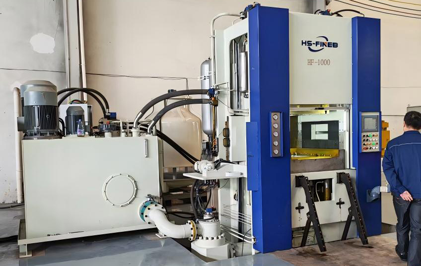
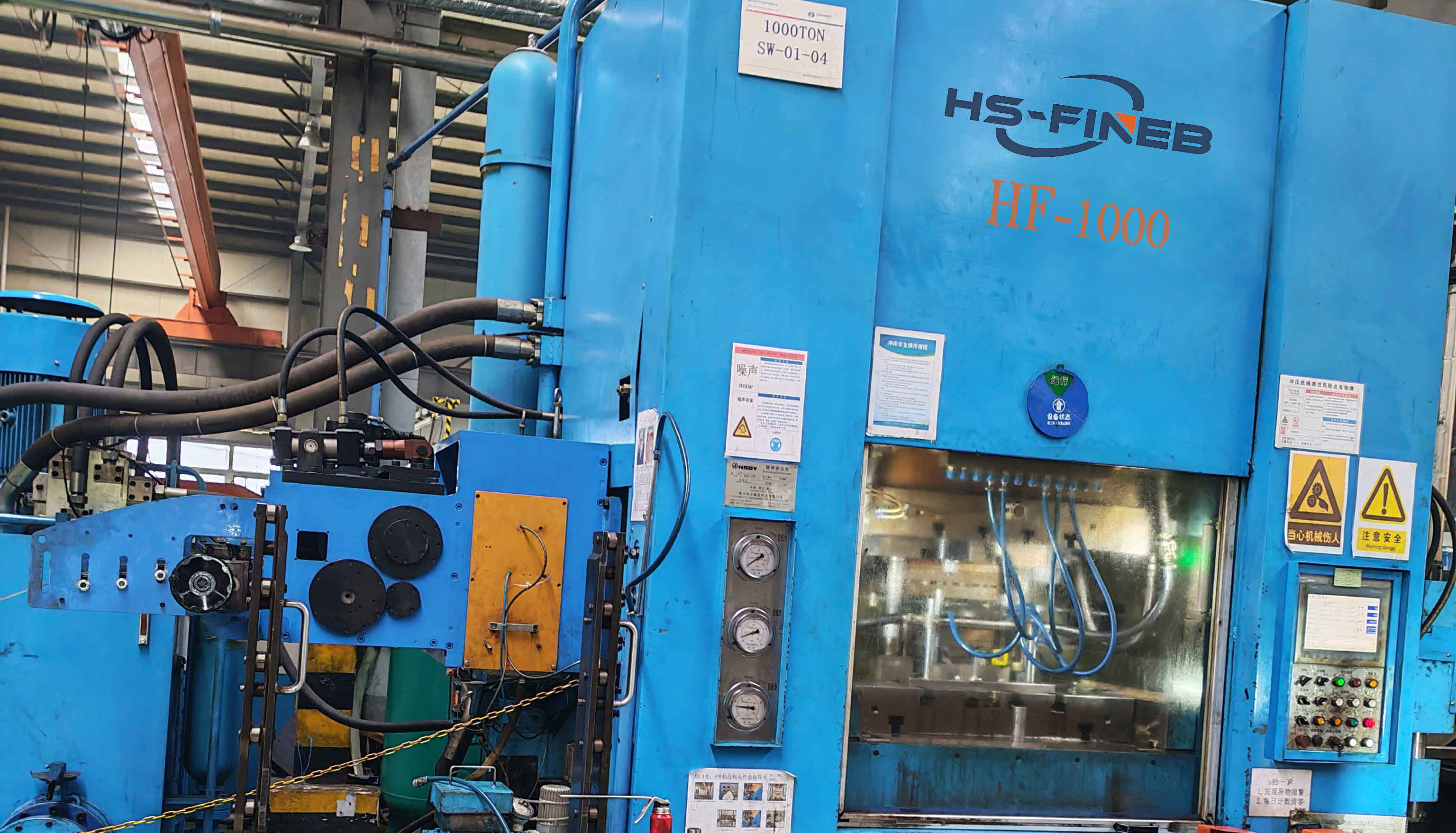
Choose the HF-1000 when part dimensions exceed 600mm blanking diameter or material thickness reaches 22mm in high-strength alloy steels. The 5000 kN ring-gear force and 2500 kN counter-pressure maintain fracture-free shear edges on S700MC and equivalent grades where conventional blanking produces torn edges requiring full-perimeter secondary machining.

The HF-1200 represents the ceiling of triple-action hydraulic fine blanking. Selected for mining wear plates, wind-turbine brake discs and rail-vehicle structural components up to 25mm in S700MC. The 6000 kN V-ring force, 3000 kN counter-pressure and 1200x1200mm working table deliver shear-edge quality on parts that no other single-stroke process can produce.
Each photo shows an HF-series press at a different build stage — from ram and column machining on the CNC floor to hydraulic-system integration and final assembly. The gallery progresses from compact 200T units to the 1200T flagship, illustrating how die-envelope dimensions and frame mass scale across the tonnage range.
| Parameter | HF-200 | HF-320 | HF-400 | HF-500 | HF-650 | HF-700 | HF-800 | HF-1000 | HF-1200 |
|---|---|---|---|---|---|---|---|---|---|
| Total Pressure (kN) | 2000 | 3200 | 4000 | 5000 | 6500 | 7000 | 8000 | 10000 | 12000 |
| Ring Gear Force (kN) | 1000 | 1600 | 2000 | 2500 | 3250 | 3500 | 4000 | 5000 | 6000 |
| Counter Pressure (kN) | 500 | 800 | 1000 | 1250 | 1625 | 1750 | 2000 | 2500 | 3000 |
| Ram Stroke | 150/100 mm | 200/150 mm | 200/150 mm | 250/180 mm | 250/180 mm | 300/200 mm | 300/200 mm | 350/250 mm | 350/250 mm |
| Stroke Frequency (/min) | 80 | 70 | 65 | 60 | 55 | 50 | 45 | 40 | 35 |
| Max Sheet Width (mm) | 250 | 300 | 350 | 400 | 450 | 500 | 550 | 600 | 700 |
| Max Thickness (mm) | 8 | 12 | 14 | 15 | 16 | 18 | 20 | 22 | 25 |
| Working Table (mm) | 500x500 | 600x600 | 650x650 | 750x750 | 850x850 | 900x900 | 950x950 | 1100x1100 | 1200x1200 |
| Main Motor (kW) | 37 | 67 | 75 | 90 | 110 | 132 | 160 | 200 | 250 |
| Weight (kg) | 14000 | 22000 | 28000 | 35000 | 45000 | 52000 | 62000 | 80000 | 98000 |
Reading the table: Total Pressure must exceed your calculated blanking force (shear perimeter x thickness x material shear strength) by at least 15% margin. Ring Gear Force determines V-ring impingement depth — insufficient force causes fracture-zone tearing on thicker or higher-strength materials. Counter Pressure controls die-roll and flatness. Stroke Frequency sets your maximum SPM; Max Sheet Width and Max Thickness define the die envelope ceiling. Specifications are standard configuration; custom stroke length, table size and control systems are available on request.
Send the part drawing with material grade, thickness and annual volume. We calculate total blanking force from shear perimeter x thickness x material shear strength — the number that determines which tonnage platforms are viable.
We cross-check your die layout against each candidate platform's working table, ram stroke and max sheet width. If the die doesn't fit the envelope or the stroke can't clear the die stack, that platform is eliminated before you invest in tooling.
Feeding pitch accuracy, coil weight capacity and deburring method are matched to the selected platform's SPM and part geometry. The press, coil feed and finishing cell are specified as one synchronized system — not as separate procurement items.
You receive a documented technical proposal: selected platform, force calculations, die-envelope confirmation, coil-feeding specification and current lead time. No ambiguity — every parameter is confirmed before the build order is placed.
Send the drawing, material grade, thickness and annual volume. Within one business day, our engineers will return the calculated blanking force, a shortlisted HF-series platform, die-envelope confirmation and a coil-feeding specification — or tell you honestly if fine blanking isn't the right process for your part.