💬 WhatsApp Chat

Fine Blanking Press Tonnage Selection: How to Calculate Required Force

Step-by-step tonnage calculation for fine blanking presses, with worked examples and HS-FINEB model selection guidance by part type and material.

Sizing Guide

Calculating Required Tonnage

Selecting the right fine blanking press tonnage is a calculation, not a guess. The total force a fine blanking press must deliver is the sum of three independently controlled forces: blanking force, V-ring impingement force and counter-pressure force. Undersizing the press means the force is insufficient — the material will not shear cleanly, edge quality drops, die-roll increases and the die may be damaged. Oversizing the press means unnecessary capital investment, but it provides headroom for future parts with larger perimeters, thicker materials or harder grades — a common practice for job shops and contract manufacturers.

The formulas below let you estimate required tonnage for any part. For a definitive calculation, our engineering team performs the analysis from your part drawings, including force distribution analysis for complex geometries and multi-station progressive dies. Contact Helen for a free tonnage assessment.

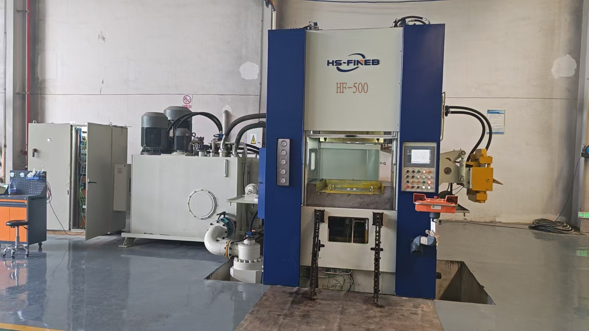
HS-FINEB HF-500 fine blanking press 500 ton for medium parts
Force Calculation

The Three Force Formulas

Blanking Force (Fb)

Fb = P × t × τ × Sf

  • P = cutting perimeter (mm) — total length of all cutting edges including outer profile, inner holes and cutouts
  • t = material thickness (mm)
  • τ = material shear strength (N/mm²) — approximately 70–80% of tensile strength
  • Sf = safety factor (typically 1.2–1.5) — accounts for die wear, material hardness variation and tool edge condition

Result in Newtons (N). Divide by 10,000 to convert to kN, or by 9,810 to convert to metric tons (T).

V-Ring Force (Fv)

Fv = 0.20 × Fb to 0.40 × Fb

The V-ring force is typically 20–40% of the blanking force, depending on:

  • Material thickness: Thicker materials require higher V-ring force to prevent lateral flow
  • Material hardness: Harder materials require higher V-ring indentation
  • Part geometry: Parts with complex profiles or tight corners need higher V-ring force to constrain material at all points

Rule of thumb: start at 30% of Fb and adjust based on die tryout results. The V-ring must indent 20–30% of material thickness to be effective.

Counter-Pressure (Fc)

Fc = 0.10 × Fb to 0.20 × Fb

The counter-pressure force is typically 10–20% of the blanking force, depending on:

  • Material ductility: Softer, more ductile materials tend to bulge more and need higher counter-pressure
  • Part flatness requirement: Tighter flatness specifications need higher counter-pressure
  • Material thickness: Thinner materials need proportionally higher counter-pressure to prevent bulging

Rule of thumb: start at 15% of Fb and verify flatness during die tryout.

Total Required Force = Fb + Fv + Fc = Fb × (1.30 to 1.60)

The total force is 130–160% of the blanking force alone, depending on material and geometry factors.

Worked Examples

Tonnage Calculations for Common Parts

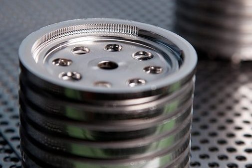
Fine-blanked precision gear and bracket parts showing typical fine blanking applications

Example 1: Spur Gear (50 mm diameter, 5 mm thick, 16MnCr5)

  • Perimeter (P): ~157 mm (gear tooth profile, approximated)
  • Thickness (t): 5 mm
  • Shear strength (τ): 370 N/mm² (16MnCr5, annealed)
  • Safety factor (Sf): 1.3
  • Fb = 157 × 5 × 370 × 1.3 = 377,615 N ≈ 378 kN ≈ 38.5 T
  • Fv = 0.30 × 38.5 = 11.6 T
  • Fc = 0.15 × 38.5 = 5.8 T
  • Total = 38.5 + 11.6 + 5.8 = 55.9 T

Recommended press: HF-200 (200T) — provides 3.6× headroom, accommodating die wear and future part changes.

Example 2: Bracket (80 mm × 40 mm, 8 mm thick, S700MC)

  • Perimeter (P): ~240 mm (outer profile)
  • Thickness (t): 8 mm
  • Shear strength (τ): 520 N/mm² (S700MC HSLA)
  • Safety factor (Sf): 1.4
  • Fb = 240 × 8 × 520 × 1.4 = 1,399,296 N ≈ 1,399 kN ≈ 142.6 T
  • Fv = 0.35 × 142.6 = 49.9 T (harder material, higher ratio)
  • Fc = 0.15 × 142.6 = 21.4 T
  • Total = 142.6 + 49.9 + 21.4 = 213.9 T

Recommended press: HF-320 (320T) — provides 1.5× headroom, adequate for this application.

Example 3: Washer (30 mm OD, 10 mm ID, 2 mm thick, C45)

  • Perimeter (P): ~125 mm (outer + inner)
  • Thickness (t): 2 mm
  • Shear strength (τ): 340 N/mm²
  • Safety factor (Sf): 1.2
  • Fb = 125 × 2 × 340 × 1.2 = 102,000 N ≈ 102 kN ≈ 10.4 T
  • Fv = 0.25 × 10.4 = 2.6 T
  • Fc = 0.20 × 10.4 = 2.1 T
  • Total = 10.4 + 2.6 + 2.1 = 15.1 T

Recommended press: HF-200 (200T) — smallest model, ample headroom for small thin parts.

Model Selection

HS-FINEB Model Mapping by Application

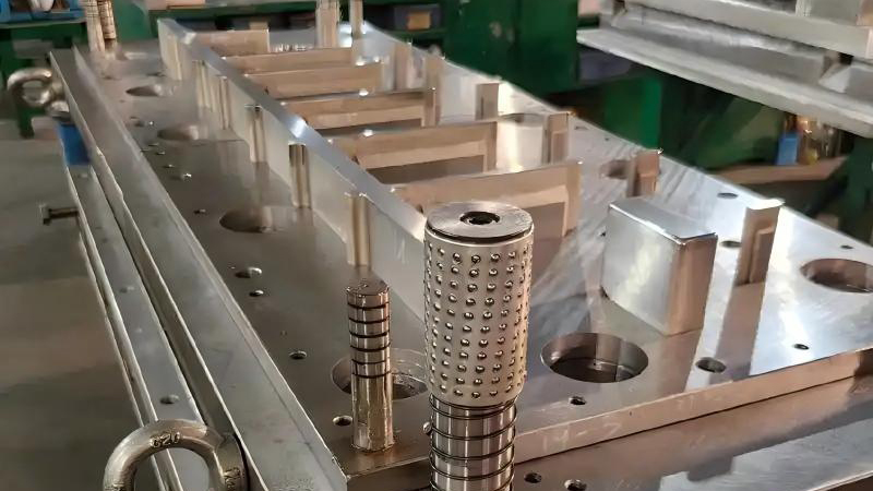
Fine blanking die and tooling showing part geometry that determines tonnage requirements

The tonnage calculation above gives the minimum required force. In practice, press selection should include a headroom factor of 1.3–2.0× the calculated total force, for three reasons:

  • Die wear: As cutting edges dull, required force increases by 10–25%. The press must handle worn-die conditions without quality degradation.
  • Material variation: Material hardness varies within a coil and between heats. The press must accommodate the upper end of the hardness range.
  • Future parts: If you plan to produce different parts on the same press — harder materials, thicker gauges, larger perimeters — headroom accommodates future applications without requiring a second press purchase.
HS-FINEB ModelRated ForceTypical Part RangeMaterial Thickness
HF-200200TSmall parts: connectors, terminals, small gears1–3 mm
HF-320320TMedium-small: brackets, washers, small caliper parts2–6 mm
HF-400 / HF-500400–500TMedium: seat mechanisms, transmission components3–8 mm
HF-650 / HF-700650–700TMedium-large: brake calipers, structural brackets5–12 mm
HF-800 / HF-1000800–1000TLarge: heavy structural parts, large gears8–15 mm
HF-12001200TVery large: thick-plate structural, chassis components10–25 mm

Why oversizing matters: A press purchased at 1.3× the current requirement can accommodate future part changes, harder materials and die wear without quality degradation. Many buyers choose a press one size larger than the minimum calculation to future-proof their investment — the price difference between adjacent models is typically 15–25%, while upgrading to a larger press later means a full new machine purchase.

Why undersizing is dangerous: Running a press at or above its rated force reduces hydraulic system life, increases frame deflection (degrading part accuracy), accelerates die wear and risks catastrophic failure. The safety factor in the blanking force formula exists for a reason — the press must have headroom beyond the nominal calculation.

For a detailed comparison of all 9 HS-FINEB models with full specifications, see our press comparison chart.

Reference Data

Material Shear Strength Chart

The tonnage calculations above depend on accurate shear strength values for the material being blanked. Shear strength (τ) is approximately 70–80% of the material's ultimate tensile strength (UTS), varying with material condition (annealed, cold-rolled, hardened) and thickness. The table below provides typical shear strength values for common fine blanking materials in the annealed condition. For work-hardened or heat-treated materials, increase the value by 20–50% depending on hardness.

MaterialGradeUTS (N/mm²)Shear Strength τ (N/mm²)
Low-carbon steelC10/C15340–420270–340
Medium-carbon steelC45560–700430–560
Alloy steel16MnCr5500–650370–500
HSLA steelS700MC750–820520–650
Stainless steel304520–720400–560
Spring steel65Mn700–900550–700
BrassC26000300–440220–330

Values are indicative for annealed condition. Always verify with your material supplier's certificate data for precise tonnage calculations.

Die Clearance

Tool Clearance & Safety Factor Selection

Determine die clearance at 0.5% of material thickness before finalizing tonnage calculations. For 5 mm material, this means 0.025 mm clearance between punch and die — tight enough to force clean shearing but not so tight as to cause galling or accelerated edge wear. The safety factor in the blanking force formula accounts for die wear over production life: as cutting edges dull, the shear zone elongates and required force increases by 10–25%. A safety factor of 1.3 is recommended for new dies in soft materials; 1.4–1.5 for harder grades like S700MC or work-hardened stainless where die wear is faster. Never operate a fine blanking press below 1.2× safety factor — the force margin protects both part quality and die integrity.

Need Help Sizing Your Press?

Send us your part drawings and material specifications. Our engineers will calculate the required tonnage and recommend the optimal HS-FINEB model for your application — at no cost.

💬