PEM fuel cell stacks contain 200–400 bipolar plates, each a 0.1–0.3 mm metallic sheet that must seal perfectly, conduct electricity, and distribute gases uniformly. Fine blanking delivers the 100% smooth shear edge that makes leak-free stacking possible — at production rates that make hydrogen energy economically viable.
A PEM fuel cell stack is a layered structure: anode plate, membrane electrode assembly (MEA), cathode plate, repeated 200–400 times under compression. Each interface between plates and MEA must seal perfectly — hydrogen on the anode side, air on the cathode side, and never the two shall meet. If they mix, the cell not only loses power output — it can be destroyed by combustion.
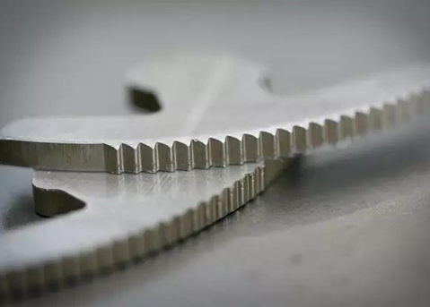
The single most critical manufacturing parameter for a metallic bipolar plate is the quality of its outer edge. A stamped plate with 30–70% shear surface leaves a fracture zone with micro-paths for gas leakage. Even a leak rate of 0.1 ml/min per plate compounds across 400 plates to 40 ml/min of hydrogen loss — enough to degrade stack efficiency by 3–5% and create safety concerns. Fine blanking eliminates this failure mode by producing 100% smooth shear edges with no fracture zone and no micro-leak paths.
This is why leading fuel cell manufacturers are shifting from hydroforming and chemical etching to fine blanking for metallic bipolar plate production. Fine blanking delivers the edge quality, flatness, and volume economics that the hydrogen economy demands as fuel cell vehicles, stationary power, and aviation applications scale toward mass production in 2026 and beyond.
A bipolar plate is not a simple sheet metal part. It is a multifunctional component that simultaneously performs three critical roles in every fuel cell.
Each plate separates hydrogen on the anode side from air (oxygen) on the cathode side. The plate's flow field channels — serpentine, parallel, or interdigitated patterns embossed into the sheet — distribute reactant gases uniformly across the MEA active area. Uneven gas distribution causes localized starvation, reducing cell voltage and accelerating MEA degradation. Plate flatness directly determines flow field uniformity.
The bipolar plate conducts electrons from the anode of one cell to the cathode of the adjacent cell. Contact resistance at the plate-to-MEA interface is a major contributor to stack voltage loss — typically 15–25 mΩ·cm². Surface flatness and smoothness directly affect contact resistance. A plate with 0.1 mm waviness increases interfacial resistance by 40–60%, directly reducing stack power output.
The plate dissipates heat from the electrochemical reaction and manages product water. In liquid-cooled stacks, the plate contains internal cooling channels; in air-cooled stacks, the flow field itself serves as the heat exchanger. Plate flatness ensures uniform thermal contact between layers — thermal hotspots from warped plates can locally overheat the MEA, causing membrane pinhole formation and premature failure.
Bipolar plates push fine blanking into a regime that most practitioners never encounter — sheet thicknesses of 0.1–0.3 mm. At these thicknesses, the margin between success and catastrophic failure shrinks to microns.
The primary material is 316L stainless steel, chosen for its excellent corrosion resistance in the acidic PEM fuel cell environment (pH 3–5 at 80 °C). For premium applications requiring maximum conductivity and minimum weight, Titanium Grade 2 is used — though at 3–5× the material cost of 316L. For economy applications, SUS304 stainless provides acceptable performance at lower cost, though with somewhat higher contact resistance and lower corrosion resistance than 316L.
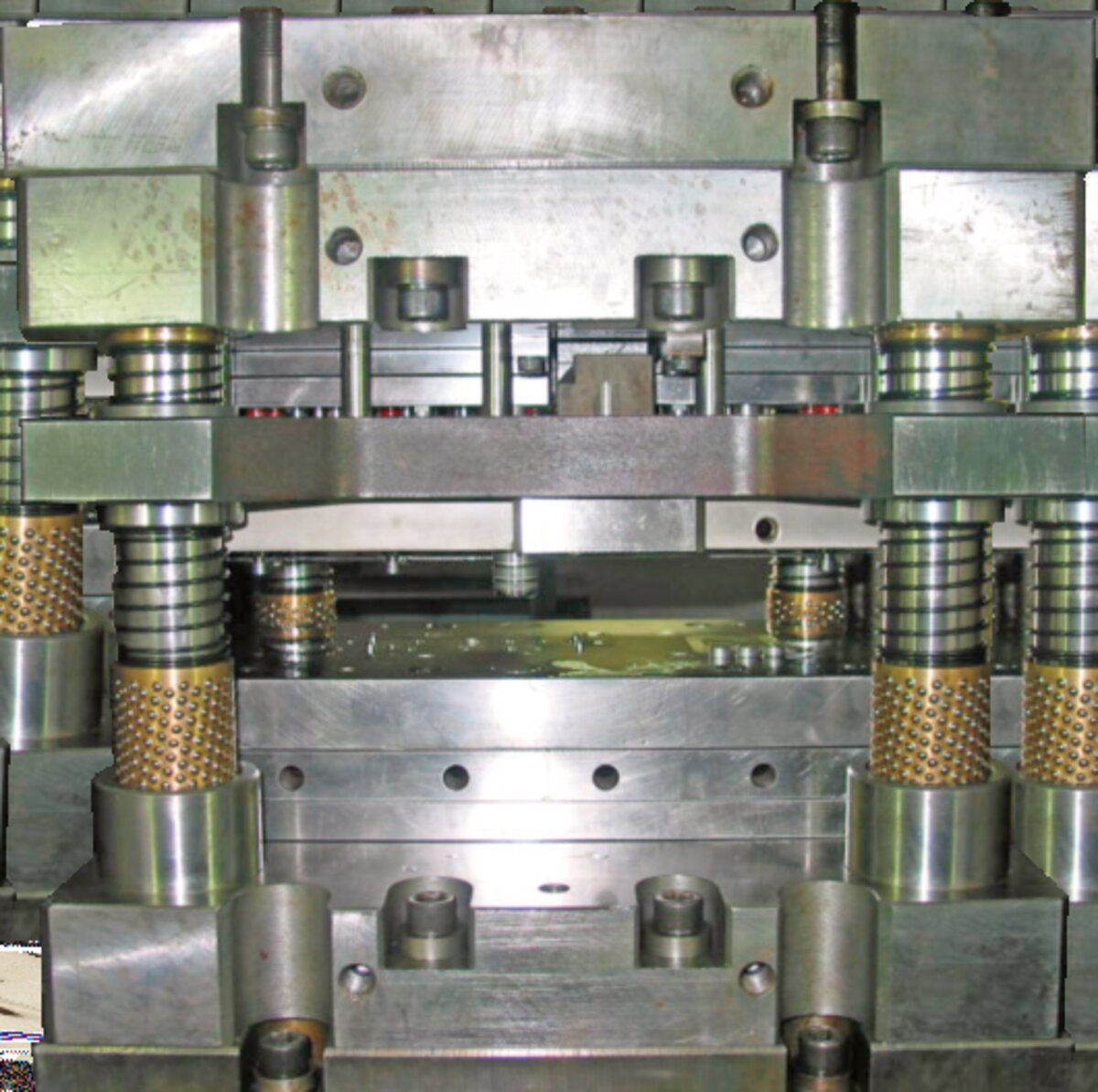
The challenge is die clearance. For 0.1 mm material, die clearance at 3–5% of thickness translates to just 0.003–0.005 mm per side. For 0.3 mm material, it ranges from 0.009–0.015 mm. This clearance must be maintained uniformly across the entire plate perimeter — often 200–400 mm in length — requiring a press frame with deflection under 0.02 mm per meter of bed width and die guidance with ball-bearing precision.
The V-ring configuration for ultra-thin material requires special optimization. Standard V-ring geometries designed for 1 mm+ material will pierce through 0.1 mm sheet rather than impinge it. Low-profile V-rings with reduced tooth height (0.1–0.2 mm) and closer spacing to the cutting edge are required, with V-ring force reduced to 15–25% of blanking force to prevent material distortion.
Four engineering advantages make fine blanking the superior process for metallic bipolar plate manufacturing.
The shear edge is the sealing surface. Fine blanking produces a fully work-hardened, mirror-finish edge with zero fracture zone. This eliminates the micro-channels where gas could escape between stacked plates. Leak rate testing on fine-blanked 316L plates measures <0.01 ml/min per plate — 10× better than stamped equivalents and meeting the <0.1 ml/min per plate specification required by automotive fuel cell stacks.
Counter-pressure during the blanking stroke holds the 0.1–0.3 mm sheet flat against the die, producing plate flatness under 0.02 mm across the entire surface. This flatness ensures uniform contact pressure in the stack, which means uniform gas distribution, uniform current density, and uniform thermal management. Stamped plates typically exhibit 0.1–0.3 mm waviness — enough to cause flow channel distortion and localized MEA degradation.
A compound fine blanking die with a stinger (forming punch) can blank the outer profile and emboss the flow field channels in a single press stroke. This eliminates the need for a separate hydroforming or embossing operation, collapsing the process chain and ensuring that channel geometry is registered precisely to the plate outline every time.
Any burr on a bipolar plate edge is a potential electrical short circuit between adjacent cells in the stack. Conventional stamping produces burr heights of 0.05–0.15 mm that must be removed by vibratory deburring or belt sanding — processes that can damage the flow channel features and add cost. Fine blanking produces burr heights under 0.005 mm, eliminating the deburring step entirely and removing the short-circuit risk.
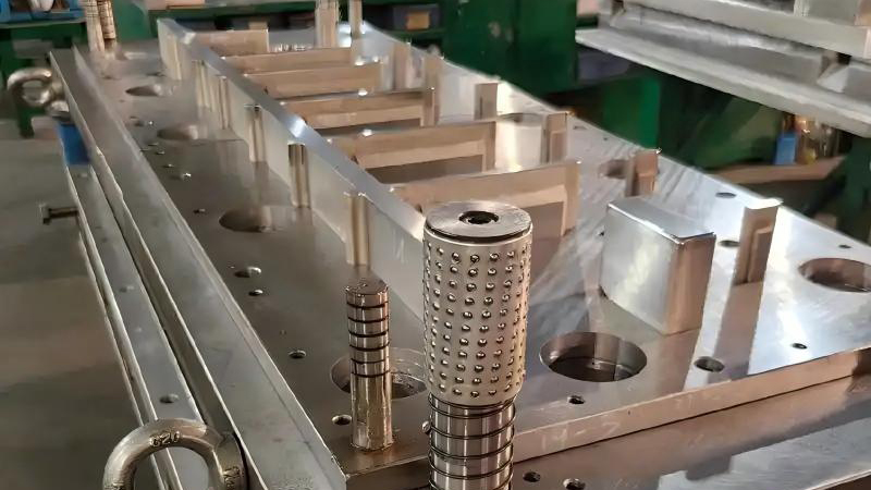
The die for bipolar plate production is a compound die — meaning it performs the blanking operation and the flow channel forming operation simultaneously in a single stroke. This requires careful engineering of the die components.
The stinger (forming punch) is integrated into the blanking die assembly. When the press descends, the V-ring engages first, clamping the ultra-thin sheet. The stinger then descends into the die cavity, embossing the flow field pattern (serpentine, parallel, or interdigitated channels) into the sheet surface. Finally, the blanking punch shears the outer profile, producing the finished plate with channels and edge in one piece.
Die coating is essential for bipolar plate production. 316L stainless and titanium are both galling-prone materials — they tend to adhere to uncoated tool steel surfaces under pressure. DLC (Diamond-Like Carbon) coating on the punch and die surfaces eliminates galling, reduces friction by 60–80%, and extends die life to 500K–1M hits between regrinds. For titanium plates, AlCrN coating provides superior performance due to its higher temperature stability and oxidation resistance.
V-ring force optimization is the most sensitive parameter for ultra-thin bipolar plate production. Too little force and the material flows laterally during shearing, creating a fracture zone. Too much force and the V-ring pierces through the 0.1 mm sheet, creating a tear rather than a clean impingement. Optimal V-ring force for 0.1 mm 316L stainless is typically 15–20% of blanking force, with low-profile V-ring tooth geometry (0.1 mm height, 0.3 mm width, 45° angle).
Material grades, thickness ranges, and die parameters for the three primary bipolar plate materials.
| Parameter | 316L Stainless (Primary) | Titanium Gr 2 (Premium) | SUS304 (Economy) |
|---|---|---|---|
| Material Thickness | 0.1–0.3 mm | 0.1–0.25 mm | 0.15–0.3 mm |
| Tensile Strength (MPa) | 480–680 | 345–450 | 520–720 |
| Yield Strength (MPa) | 170–310 | 275–410 | 205–310 |
| Die Clearance (% of t) | 3–5% | 3–4% | 3–5% |
| Die Clearance (mm for 0.1mm t) | 0.003–0.005 | 0.003–0.004 | 0.003–0.005 |
| V-Ring Force (% of blanking) | 15–25% | 20–30% | 15–25% |
| Counter-Pressure (% of blanking) | 25–35% | 30–40% | 25–35% |
| Recommended Die Coating | DLC | AlCrN | DLC or TiCN |
| Die Life per Regrind | 500K–1M hits | 300K–600K hits | 500K–800K hits |
| Production Rate (SPM) | 30–60 | 20–40 | 30–60 |
| Contact Resistance (mΩ·cm²) | 10–20 | 5–10 | 20–35 |
| Corrosion Rate (µm/year) | <0.5 | <0.1 | 1–3 |
Three competing processes can manufacture metallic bipolar plates. Only fine blanking delivers both technical performance and volume economics.
| Cost Factor | Fine Blanking | Hydroforming | Chemical Etching |
|---|---|---|---|
| Cost per Plate | $0.50–$2.00 | $2.00–$5.00 | $5.00–$15.00 |
| Production Rate | 30–60 SPM | 5–15 SPM | Batch (hours) |
| Shear Edge Quality | 100% smooth shear | N/A (formed, not cut) | Etched (rough) |
| Burr Height | <0.005 mm | 0.02–0.05 mm | 0.05–0.1 mm |
| Flatness | <0.02 mm | 0.05–0.1 mm | 0.05–0.15 mm |
| Flow Channel Formation | Same stroke (compound die) | Primary operation | Primary operation |
| Secondary Operations | None | Trimming + deburring | Cleaning + passivation |
| Tooling Cost | $15K–$50K | $8K–$30K | $2K–$10K (photo mask) |
| Material Utilization | 60–75% | 70–85% | 80–95% |
| Environmental Impact | Low (no chemicals) | Low | High (acid waste) |
| Annual Capacity (1 press line) | 10M–30M plates | 1M–3M plates | 0.5M–1M plates |
Send us your plate drawings, flow channel specifications, and target production volume. We will evaluate fine blanking feasibility, recommend the press, compound die, and coating configuration, and provide a per-plate cost comparison versus your current process.