💬 WhatsApp Chat

Die Life & Resharpening Intervals

Waiting for an obvious failure to schedule resharpening is the expensive way to manage die life. Edge quality degrades gradually — long before it becomes a visible defect on the part. This guide covers the factors driving die wear, expected life by material, the resharpening process, and how die coatings extend the interval between regrinds.

Die Wear

Factors Affecting Fine Blanking Die Life

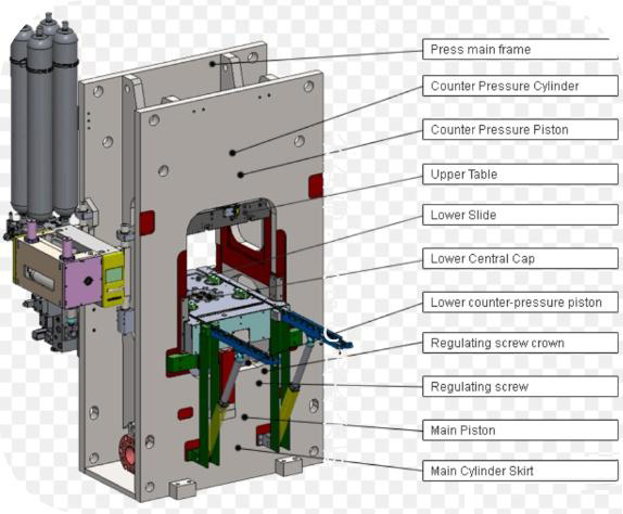
A fine blanking die is not a single component — it is a precision assembly of punch, die plate, V-ring plate, stripper, and counter-piston, each with its own wear profile. Die life is determined by the interaction of five primary factors, and two identical dies running different material batches can have meaningfully different service intervals even at the same stroke count.

Fine blanking die assembly showing punch, die plate, V-ring, and counter-piston components
Life Factors

Five Factors That Determine Die Life

Material Type & Hardness

The single largest factor. High-strength steels (yield above 600 MPa) generate higher cutting forces and more abrasive wear per stroke than low-carbon steel. Stainless steel (work-hardening grades like 304/316) galls the die surface, accelerating wear beyond what the base hardness alone would predict. Nickel-based superalloys (Inconel) are both hard and abrasive, reducing die life by 60–80% compared to carbon steel of the same thickness.

Material Thickness

Thicker material means more contact surface area per stroke between the cutting edge and the workpiece. A 6 mm thick part wears the cutting edge approximately twice as fast as a 3 mm part of the same material, because the rubbing distance per stroke is doubled. Above 8 mm, the V-ring engagement force increases proportionally, accelerating V-ring wear in addition to cutting edge wear.

Lubrication

Fine blanking lubricant serves two functions: reducing friction between cutting edge and material, and flushing wear debris from the die clearance zone. Inadequate lubrication causes adhesive wear (galling) on the cutting edge, particularly with stainless and high-strength steel. Lubricant viscosity, application method (roller coating vs. spray), and flow rate all affect die life. A consistent lubricant film can extend die life by 30–50% over intermittent application.

Die Material & Heat Treatment

The die steel grade and its heat treatment determine the baseline wear resistance. D2 tool steel (DIN 1.2379) at HRC 60–62 is the standard for fine blanking dies — high carbon, high chromium, excellent wear resistance. PM (powder metallurgy) steels like Vanadis 4 Extra or S390 offer 30–60% longer life than conventional D2 at higher cost. Carbide inserts (tungsten carbide) provide the longest life but are limited to simpler geometries due to their brittleness.

Clearance & Alignment

The cutting clearance between punch and die (typically 0.5% of material thickness) must be uniform around the entire cutting perimeter. Misalignment concentrates wear on one side of the die, reducing life by 40–70%. The press guidance system — four-pillar or eight-pillar with preloaded ball bearings — maintains punch-to-die alignment within 0.005 mm under full load. Our fine blanking technology page covers the press architecture that enables this precision.

Die Life by Material

Expected Die Life Ranges by Material

The table below provides expected die life between resharpenings for a standard D2 tool steel die (HRC 60–62) running typical automotive volumes. Actual life varies with the factors above — these ranges are starting references, not guarantees.

MaterialTypical ThicknessStrokes Before ResharpeningKey Wear Mode
C45 (Medium Carbon Steel)2–6 mm300,000 – 500,000Adhesive wear on cutting edge; gradual V-ring rounding
16MnCr5 (Case-Hardening Steel)2–5 mm200,000 – 400,000Adhesive + abrasive wear; higher cutting force accelerates edge dulling
Stainless 304/3161–4 mm100,000 – 250,000Galling and adhesive pickup on die surface; requires frequent polishing
High-Strength Steel (≥600 MPa)2–6 mm150,000 – 300,000Abrasive wear; cutting edge chipping at stress concentrations
Inconel / Nickel Superalloys1–3 mm50,000 – 100,000Severe abrasive + adhesive wear; carbide inserts strongly recommended
Aluminum (5xxx/6xxx)1–4 mm500,000 – 1,000,000Low wear; die life often limited by material buildup (adhesion) rather than abrasion
Reference insight: These figures assume a properly maintained die running under consistent lubrication on a well-aligned press. The ranges are wide because the other four factors (thickness, lubrication, die material, clearance) shift the actual life by 2–3x within the same material grade. For a specific die life estimate on your material and part geometry, see our materials guide or contact our tooling team with your part drawing.
Early Indicators

Early Wear Indicators: Before a Part Is Visibly Out of Spec

Stroke count alone is not a reliable resharpening trigger. Two identical dies running different material batches can have meaningfully different real service intervals. Tracking the wear indicators below alongside stroke count catches the need for resharpening before quality degrades to scrap.

Burr Height Creep

A gradual increase in burr height over thousands of strokes — well before it crosses the part’s acceptance threshold — is usually the first measurable sign of V-ring or die-edge wear. Burr height should be monitored with a calibrated gauge on a defined sample frequency (e.g., every 5,000 strokes). An upward trend of 0.01 mm per 20,000 strokes indicates the die is approaching resharpening.

Increasing Cut Force

If the press’s tonnage monitoring shows blanking force trending upward for the same material and thickness, edge wear is a common cause — the dull edge requires more force to initiate the cut. Our HF-series presses log force per cycle; a 5–8% increase above baseline triggers a tooling inspection.

Surface Finish Degradation

A cut surface that is visibly rougher or less consistent than it was early in the die’s life — with no material or process change to explain it — indicates cutting edge wear. Surface roughness should be measured with a profilometer on the shear edge; Ra increasing from 0.4 μm to 0.8 μm is the threshold for scheduling resharpening.

Dimensional Reject Trend

A slow uptick in dimensional rejects, especially concentrated near end-of-tolerance rather than randomly distributed, correlates with cumulative die wear rather than random process variation. When the rejection rate shifts from 0.1% to 0.5%, the die should be pulled for inspection before the rate reaches 1% — at which point you have already accumulated scrap.

Resharpening Process

The Resharpening Process: When, How Much, How Often

Resharpening Protocol

Resharpening restores the cutting edge by removing the worn surface layer and re-establishing the original edge geometry. The process requires precision grinding — the cutting edge must be reground to its original sharpness (edge radius under 0.005 mm) without altering the die clearance or V-ring profile.

When to Resharpen

Resharpen at the first sign of the wear indicators above — not at a fixed stroke count. However, if no monitoring system is in place, the die life table above provides the maximum stroke count before mandatory inspection. A die pulled for scheduled resharpening at the first indicator is a planned, short interruption (2–8 hours depending on die complexity). A die run to failure is an unplanned stoppage, often with accumulated scrap from the run-up to the failure.

How Much to Remove

Typical removal per resharpening: 0.05–0.15 mm from the cutting edge surface. This removes the worn layer (work-hardened surface, micro-cracks, adhesive deposits) and restores the edge geometry. Removing too little leaves residual wear and shortens the next interval; removing too much wastes die material and reduces total die life (number of resharpenings possible before the die is below minimum working thickness). A well-maintained D2 die can typically be resharpened 15–25 times before retirement.

Re-Coating After Resharpening

If the die has a PVD coating (TiN, TiCN, AlCrN), the coating must be stripped before grinding (the coating is harder than the grinding wheel and will damage it) and re-applied after. Re-coating adds 0.5–2 days to the turnaround but restores the coating’s wear-reduction benefit for the next production interval. Learn more about die construction in our die design guide.

Precision grinding of fine blanking die cutting edge during resharpening process
Die Coatings

Die Coating Options and Their Effect on Life

PVD (Physical Vapor Deposition) coatings deposit a thin, hard layer on the die surface that reduces adhesive wear, galling, and abrasive wear. The coating does not change the die’s geometry — layer thickness is 2–5 μm — but it dramatically extends the interval between resharpenings.

CoatingHardness (HV)Max Service TempLife ImprovementBest Suited For
None (bare D2)~700 HVN/ABaseline (1x)Low-volume, low-stress applications; aluminum; soft non-ferrous
TiN (Titanium Nitride)2,000–2,400 HV500°C1.5–2xGeneral-purpose coating; carbon steels; standard automotive volumes
TiCN (Titanium Carbonitride)3,000–3,500 HV400°C2–3xHigher hardness than TiN; high-strength steel; thicker materials (4–8 mm)
AlCrN (Aluminum Chromium Nitride)3,000–3,400 HV1,100°C2.5–3.5xHigh-temperature resistance; stainless steel; prevents galling on work-hardening grades
DLC (Diamond-Like Carbon)3,000–5,000 HV350°C3–4xAluminum, stainless; lowest friction coefficient; prevents material adhesion
Coating selection insight: AlCrN is our preferred coating for stainless steel fine blanking — its oxidation resistance and anti-galling properties reduce adhesive wear, which is the dominant failure mode for work-hardening grades. TiN remains the cost-effective baseline for carbon steel; its 1.5–2x life improvement at moderate cost makes it the default for most automotive fine blanking programs. For Inconel and nickel superalloys, carbide inserts with AlCrN coating are strongly recommended over coated tool steel — the base material hardness of D2 is insufficient for these applications regardless of coating.
Total Die Life Management

Total Die Life: Planning Around Resharpening, Not Reacting to It

Total die life is the sum of all production strokes across all resharpening intervals — not the strokes between any single regrind. A die that runs 300,000 strokes per interval with 20 resharpenings provides 6,000,000 total strokes of production. Managing total die life means planning the resharpening schedule, die inventory, and regrind turnaround as an integrated system, not treating each resharpening as an emergency.

Scheduled vs. Reactive

A die pulled for scheduled resharpening at the first wear indicator is back in production in 2–8 hours with zero scrap accumulation. A die run to failure produces 0.5–2% scrap in the run-up to the failure, requires an emergency regrind (24–48 hour turnaround at premium cost), and may have secondary damage (chipped edge, V-ring deformation) that shortens the die’s remaining life.

Spare Die Strategy

For high-volume programs, a spare die set (or spare punch and die plate) allows production to continue during resharpening. The production die is swapped out at the scheduled interval, the spare goes in, and the worn die goes to the grinding shop with no line stoppage. The spare investment is justified at volumes above 500,000 parts per year, where each day of press downtime costs more than the die amortization.

Die Life Tracking System

If your process does not currently track wear indicators systematically, start with a simple burr-height spot-check on a defined stroke-count schedule — every 10,000 strokes, measure burr height on 5 parts. This catches 80% of the value at minimal effort. For full automation, the press CNC’s force-monitoring data provides continuous wear tracking without operator intervention.

Management insight: Die life management is part of the total fine blanking process — not an isolated tooling concern. The press, the die, the material, and the lubrication form a system where each component’s condition affects the others. A well-maintained die running on a well-aligned press with consistent lubrication will reach the upper end of the life ranges in the table above. The same die on a press with worn guidance, intermittent lubrication, or misaligned clearance will reach the lower end — or below. See our materials guide for material-specific die life factors and our die design page for how die construction choices affect total life.

Questions About Your Die’s Service Life?

Send us your material, part geometry, and current stroke history. Our tooling team will provide a realistic die life estimate, resharpening interval recommendation, and flag any material-specific or die construction factors that affect your program.

💬