Progressive die fine blanking for high-volume production: how multi-station presses compare with single-station, and when each approach maximizes productivity and quality.
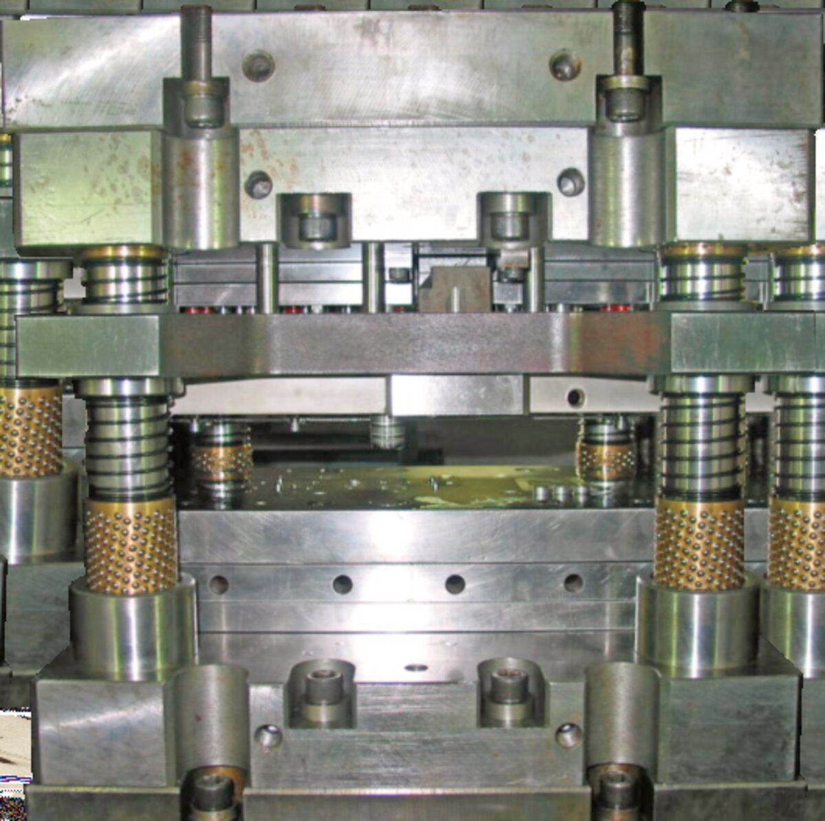
A multi-station fine blanking press executes multiple operations — piercing, blanking, forming, coining, bending — simultaneously across consecutive stations within a single progressive die. As the strip advances one pitch per stroke, each station performs its operation on a different part, and a finished part exits the final station with every press cycle. This contrasts with single-station fine blanking, where one compound die performs all cutting operations in a single stroke but produces only one part per cycle.
The productivity advantage is substantial: a multi-station progressive die on a fine blanking press can produce complete parts at 30-60 strokes per minute (SPM), compared to 10-20 SPM for single-station compound dies. For a 5-station progressive die running at 40 SPM, this means 40 finished parts per minute — 2,400 per hour, 19,200 per shift. The trade-off is increased tool complexity, higher initial die cost, and the requirement for precise strip feeding and pilot registration to maintain station-to-station accuracy.
Multi-station fine blanking is the preferred approach for high-volume production of complex parts with multiple features — transmission gears with pre-pierced bolt holes, seat recliner mechanisms with formed teeth and coined surfaces, lock components with pierced keyways and blanked profiles. For each of these applications, the progressive die eliminates secondary machining operations and produces a finished part at every stroke.

A compound die performs all cutting operations — outer blanking, inner piercing — in a single stroke at one station. The part is fully formed in one press cycle, with all features produced simultaneously rather than sequentially. Advantages include simpler die construction, lower die cost (typically 40-60% of a progressive die for the same part), superior flatness (the part is constrained throughout the stroke), and easier die maintenance. Production rate is limited to 10-20 SPM because each stroke produces one part and the full blanking force is concentrated at one station. Best suited for: prototype and low-volume production (below 100,000 parts/year), very large parts that would require an impractically large progressive die, thick materials (above 8 mm) where progressive die station forces become excessive, and parts requiring exceptional flatness.
A progressive die distributes operations across multiple stations, with each station performing one or two operations. The strip advances one pitch per stroke, and a finished part exits the final station with every cycle. Advantages include 3-5 times higher production rate (30-60 SPM), ability to incorporate forming and coining operations that cannot be done in a compound die, and reduced per-part tooling cost at high volume. Die cost is higher ($40,000-$150,000 for a typical 5-station progressive die vs $20,000-$60,000 for a compound die), and die maintenance is more complex. Best suited for: annual volumes above 100,000 parts, parts with multiple features (holes, forms, cutouts), thin to medium gauge materials (0.5-6 mm), and parts where secondary machining must be eliminated.

Strip layout design is the foundation of progressive die engineering. The layout defines the number of stations, the operation sequence, the pitch (distance between corresponding points on consecutive parts), and the material utilization percentage. A well-designed strip layout balances several competing requirements: minimizing scrap (material typically represents 40-60% of total part cost), maintaining sufficient strip strength between stations to prevent distortion during transfer, providing pilot hole locations for strip registration, and sequencing operations to avoid interfering with subsequent stations.
Typical progressive fine blanking dies have 3-8 stations. The first station usually pierces pilot holes and any functional holes; intermediate stations perform forming, coining or bending operations; the final station shears the finished part from the strip. Material utilization ranges from 40% for simple geometries to 75% for optimized layouts with nested part orientations.
Force calculation for a multi-station die must account for the fact that multiple stations are active simultaneously — but not all stations fire at the same point in the stroke. The total force at any instant is the sum of forces from all stations that are actively cutting or forming at that instant. For a 5-station die where stations are spaced one pitch apart, the force overlap depends on the shear length at each station and the material thickness. A conservative estimate assumes 60-80% of total station forces act simultaneously, as the shear phase at each station overlaps with adjacent stations' approach or return phases.
V-ring force and counter-pressure must also be calculated for the total active shear length. The V-ring surrounds each cutting contour, so total V-ring force is proportional to the total cutting perimeter at all active stations.
Multi-station fine blanking requires precise coil feeding with pitch accuracy of ±0.05 mm or better. The feeding system — typically a servo-driven roll feed (Lenze servo motor on HS-FINEB presses) — advances the strip one pitch per stroke, synchronized with the press cycle. The feed must occur during the die opening phase (when the ram is above the strip) and complete before the ram descends. Feed speed must match the press SPM: at 40 SPM with a 50 mm pitch, the feed must advance 2,000 mm/second, requiring high-torque servo motors and precision roll gripping. Strip lubrication is applied upstream of the feed, and a strip edge guide maintains lateral positioning within ±0.1 mm.
Pilot registration corrects any feed pitch error before the punch enters the material. Pilot pins — tapered punches that engage precision-pierced holes in the strip — are mounted at one or more stations and enter the pilot holes before the cutting punches contact the material. As the ram descends, the pilot pins engage first, pulling the strip into exact position. The feed system's pitch accuracy of ±0.05 mm is corrected to ±0.01 mm by the pilot registration. This is critical for multi-station dies: without pilot registration, pitch errors accumulate across stations, causing feature misalignment between operations performed at different stations.
The scrap skeleton remaining after blanking must be chopped for recycling. A scrap shear at the die exit cuts the skeleton into 100-200 mm lengths, synchronized with the press cycle at 1:1 or 1:2 stroke ratio. For materials above 4 mm, the scrap shear is hydraulically actuated.
Finished parts must be ejected from the die without damage. Blow-off nozzles or mechanical kickers push the part onto a chute or conveyor. For parts with critical surface finish, the collection system may include soft landing pads. Part presence sensors verify ejection before the next cycle — a safety interlock preventing die damage from double-feeding.
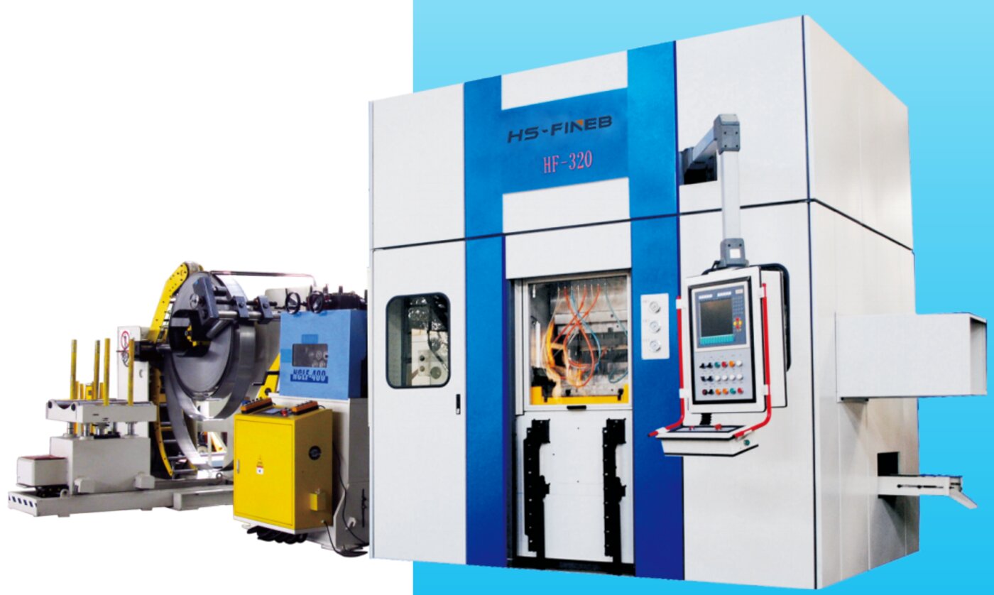
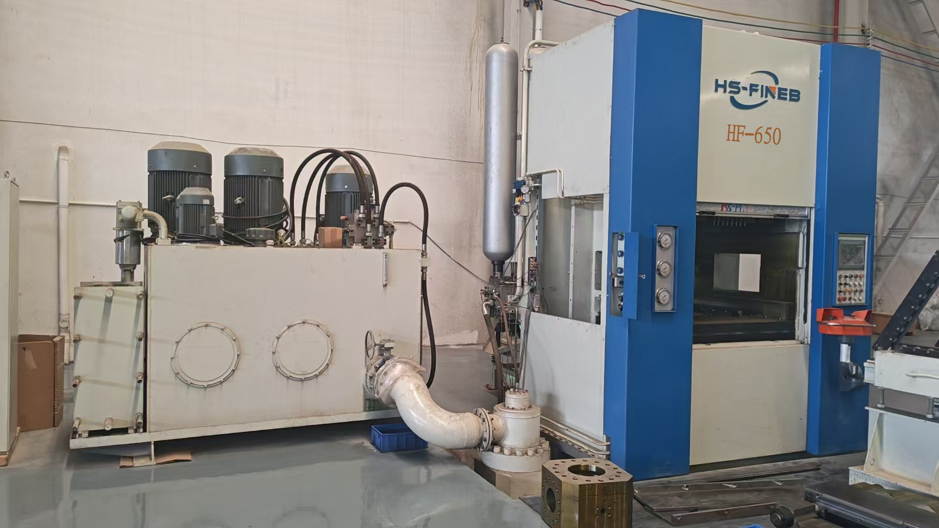
HS-FINEB presses from the HF-400 model upward support multi-station progressive dies, provided the die area, shut height range and tonnage are adequate for the specific application. The HF-400 (400 ton) accommodates progressive dies up to 600 × 500 mm die area; the HF-650 (650 ton) handles dies up to 800 × 600 mm; the HF-800 and HF-1000 extend die area to 1,000 × 800 mm for large multi-station tools. Shut height adjustment is motorized with digital readout, enabling quick die changes between progressive and compound tools.
All HS-FINEB HF-series presses feature servo-driven coil feeding (Lenze drives) with programmable pitch, pilot hole sensing, and synchronized scrap shear. The CNC controller manages the feeding cycle within the press stroke: feed starts when the ram reaches upper position, completes before the ram descends past the pilot entry point, and pilot sensors confirm engagement before cutting begins. This integrated control eliminates the need for a separate feed controller.
For applications requiring multi-station progressive dies, we recommend selecting a press model with at least 20% tonnage reserve above the calculated total force. This reserve accommodates material hardness variations, tool wear that increases cutting force, and the force overlap from adjacent stations. Our engineering team provides detailed force calculations and press sizing recommendations as part of the die design review process.

Annual volume exceeds 100,000 parts — the die cost premium is recovered through higher production rate. Part geometry includes multiple features (holes, forms, cutouts) requiring multiple operations or secondary machining. Material thickness is 0.5-6 mm, where progressive die forces are manageable. The part can be nested with acceptable material utilization (above 50%). Eliminating secondary machining (hobbing, drilling, milling) justifies the progressive die investment.
Annual volume is below 100,000 parts — the progressive die cost premium cannot be recovered within the die's service life. Part geometry is simple (one or two features) producible in a single compound stroke. Material thickness exceeds 8 mm, where progressive die forces become excessive. Part size is very large (above 200 mm), exceeding practical die area limits. Exceptional flatness is required — compound dies constrain the part throughout the stroke, producing superior flatness.
Send us your part drawing, material spec and annual volume — our engineers will recommend the optimal die architecture and press model for your production requirements.