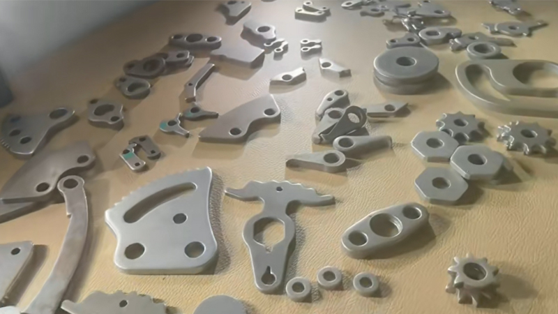
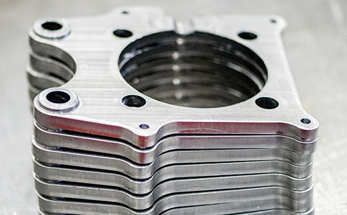
Brake caliper bodies and mounting plates demand 100% shear edges, flatness under 0.05mm, and zero die-roll — because brake components are safety-critical parts where edge fracture can cause catastrophic failure.
Brake caliper components are among the most safety-critical parts in any vehicle. A caliper body half or mounting bracket that fractures under braking load is not merely a defective part — it is a liability that can cause uncontrolled vehicle deceleration failure. This is why brake component manufacturing demands 100% shear edges with no tear-through zones, die-roll below 0.05mm, and flatness tolerances that ensure the caliper halves seat perfectly under bolt preload.
Conventional stamping cannot meet these requirements. The conventional stamping process produces a part with 30-50% tear-through zone on the cut edge — the rough, fractured surface where the material tears rather than shears. Under cyclic braking loads, this torn surface becomes an initiation point for fatigue cracks. Fine blanking eliminates this failure mode entirely by producing a 100% shear surface through the full material thickness, with no tear zone and no crack initiation sites.
Beyond edge quality, fine blanking also delivers the dimensional accuracy that brake assemblies require: flatness of 0.05mm across the caliper body face ensures uniform piston seal compression, parallelism of 0.03mm between mounting surfaces ensures even pad wear, and bore concentricity at IT7 ensures piston alignment. These tolerances are routine for fine blanking but require extensive secondary machining after conventional stamping. For more on automotive braking component applications or fine blanking's technology fundamentals, visit our overview pages.
Modern disc brake calipers comprise several distinct fine-blanked components, each with specific geometry and tolerance requirements:

| Parameter | Specification | Measurement Method |
|---|---|---|
| Flatness (caliper body face) | 0.05mm max | CMM or surface plate + dial indicator |
| Parallelism (mounting surfaces) | 0.03mm max | CMM across bolt hole centers |
| Bore concentricity | IT7 (0.02mm at 50mm PCD) | Bore gauge + CMM |
| Edge quality (shear surface) | 100% shear, zero tear zone | Visual + surface roughness (Ra <1.6µm) |
| Die-roll | <0.05mm (5% of 10mm thickness) | Optical comparator or profilometer |
| Burr height | <0.03mm (removed in deburring) | Tactile gauge |
These tolerances are achieved directly off the fine blanking press for edge quality, flatness and die-roll. Bore concentricity and diameter are achieved by CNC boring the fine-blanked hole blanks. See our die design page for the compound die approach that combines outer profile and bore blanks in a single stroke.
Case hardening steel for caliper body halves. Carburized after blanking to achieve 58-62 HRC surface with tough core. The most common caliper material in European and Asian vehicle platforms. Annealed blanking hardness: 160 HB max.
Boron-alloyed quench and temper steel for high-strength mounting brackets. After blanking, austenitized at 860°C and quenched to 450-500 HB for tensile strength above 1200 MPa. Excellent fine blanking behavior in the normalized condition.
Thermomechanically rolled HSLA steel for brackets and structural plates. Yield strength 420 MPa minimum, good weldability. No heat treatment required after blanking — strength is achieved in the as-rolled condition. Fine blanking hardness: 180 HB max.
Spring steel for pad return springs and anti-rattle clips. Quenched and tempered to 45-50 HRC after blanking. Fine blanked in the annealed condition (max 200 HB), then heat-treated to final hardness for spring function.
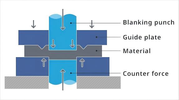
Brake caliper plates are thick — typically 8-12mm, sometimes up to 14mm for heavy-duty applications. This thickness range pushes the limits of standard single V-ring configurations. At 10mm material thickness, a single V-ring at 30-40% of thickness produces impingement depth of 3-4mm, which may not fully constrain material flow across the full thickness.
The solution is a double V-ring configuration: an inner V-ring positioned 2-3mm from the cutting edge and an outer V-ring positioned 5-7mm from the cutting edge. The two rings impinge the material at staggered depths, creating a compound clamping zone that prevents lateral material flow across the entire thickness. This configuration reduces die-roll from the typical 8-10% (of thickness) for single V-ring to under 5% for double V-ring on 10mm material.
V-ring geometry for thick material: inner ring protrusion 2.5mm at 60° included angle, outer ring protrusion 1.5mm at 45° included angle. The distance between rings is 3-4mm, and the outer ring distance from the cutting edge is 5-7mm depending on part geometry. See our die design guide for V-ring dimensioning charts.

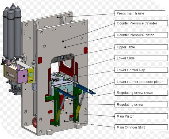
Counter-pressure is the third force in fine blanking's triple-force system, applied through the ejector pin on the die side. For brake caliper plates, counter-pressure must be set to 30-40% of the blanking force — higher than the 20-30% used for thin sheet — to minimize die-roll on thick material.
The counter-pressure plate contacts the entire part surface during the blanking stroke, preventing the part from bowing or distorting as it is sheared from the strip. For a 10mm thick caliper plate with 800T blanking force, counter-pressure is set to 240-320T. This force level requires a press with independent, programmable counter-pressure control — a standard feature of all HF-series presses.
Proper counter-pressure also ensures that the piston bore blanks (pierced simultaneously with the outer profile in a compound die) maintain concentricity with the outer profile. Without adequate counter-pressure, the bore punch deflects during piercing, producing a bell-mouthed hole that requires excessive CNC stock removal to correct.


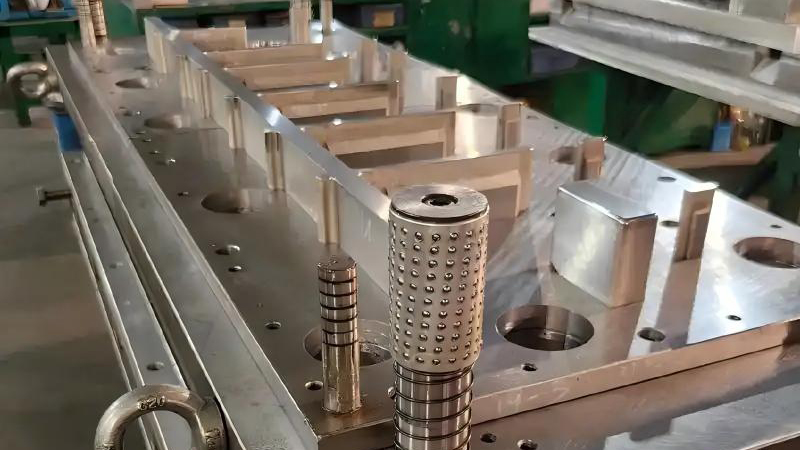
The caliper body half is produced in a compound die — a single-station die that pierces the piston bore blanks and blanks the outer profile in one press stroke. Unlike a progressive die (which moves the part through multiple stations), the compound die completes all operations at one station, ensuring maximum geometric relationship accuracy between features.
The compound die for a caliper body half comprises: the outer blanking punch (wire-EDM cut to the caliper profile with carbide inserts at high-wear areas), the V-ring stinger plate (double V-ring configuration for 10mm material), the piston bore piercing punches (2-4 punches depending on caliper type, positioned relative to the outer profile), and the counter-pressure ejector (supports the part during shearing and ejects it after the stroke).
Die life for 16MnCr5 caliper bodies with carbide inserts: 200,000-400,000 strokes. The carbide inserts are replaceable without removing the die from the press, reducing downtime to 2-4 hours for a complete insert change. Die maintenance schedule: inspect every 10,000 strokes, regrind or replace inserts every 50,000-80,000 strokes depending on wear measurement.
| Component Type | Material & Thickness | PCD (mm) | Force Range (T) |
|---|---|---|---|
| Passenger caliper body half | 16MnCr5, 8-10mm | 80-110 | 500-650 |
| SUV/light truck caliper body | 16MnCr5, 10-12mm | 110-140 | 650-800 |
| Heavy-duty caliper body | 28MnB5, 12-14mm | 140-180 | 800-1000 |
| Mounting bracket (passenger) | S420MC, 8-10mm | 80-120 | 400-550 |
| Mounting bracket (heavy-duty) | 28MnB5, 12-14mm | 120-160 | 650-900 |
Force values include blanking force + V-ring force (35%) + counter-pressure (35%). A 20% reserve capacity should be added when selecting the press model.
Fine blanking produces the caliper body blank with the outer profile, piston bore locations, and mounting holes at near-final accuracy. The one operation that cannot be completed in the blanking stroke is the final piston bore — the bore diameter, surface finish, and cylindricity require CNC machining after blanking.
The typical post-blanking process for a caliper body half:
The key advantage: fine blanking provides a blank with location accuracy that allows CNC boring to remove only 0.25mm per side — versus 2-3mm per side when boring from a cast or forged blank. This reduces CNC cycle time and tool wear significantly. See our deburring and polishing page for post-processing details.

| Cost Factor | Fine Blanking + CNC Bore | Full CNC from Billet |
|---|---|---|
| Material utilization | 65-75% (from coil/plate) | 25-40% (billet machining) |
| Material cost per part | Baseline | +60-100% |
| Cycle time per part | 2-4 seconds (blanking) + 60s (CNC bore) | 3-5 minutes (full CNC) |
| Operator requirement | 1 operator per press + CNC cell | 1 operator per CNC |
| Tooling cost | High (die) amortized over 200K+ parts | Low (no die) but high per-part |
| Break-even volume | ~10,000 parts/year | Below 5,000 parts/year |
At production volumes above 10,000 caliper bodies per year, the fine blanking + CNC route delivers 40-60% material savings and 50-70% cycle time reduction compared to full CNC machining from billet. The die investment is recovered within the first 20,000-30,000 parts.
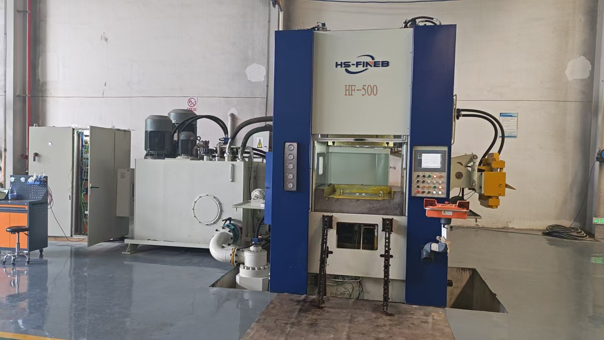
For passenger car caliper body halves in 8-10mm 16MnCr5. The 500T force with programmable counter-pressure handles the compound die for outer profile and piston bore blanks in one stroke.
View HF-500
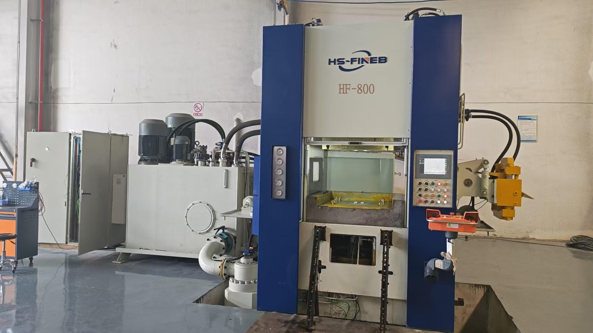
For SUV and light truck caliper bodies in 10-12mm material. The 800T capacity accommodates the higher blanking force of thicker plates while maintaining counter-pressure for minimal die-roll.
View HF-800
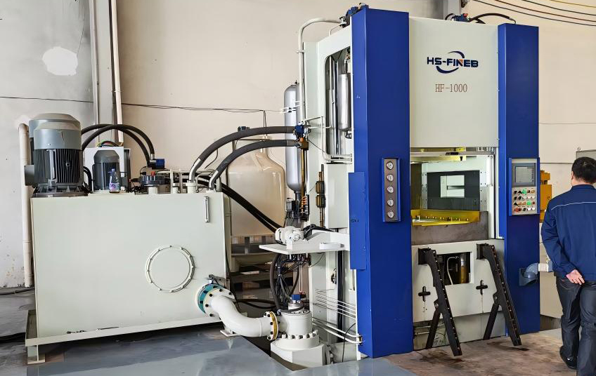
For heavy-duty commercial vehicle caliper bodies in 12-14mm 28MnB5. The 1000T force handles the most demanding caliper geometries with full double V-ring and high counter-pressure configuration.
View HF-1000Send your caliper drawing, material grade, thickness specification and target volume. Our engineers will assess fine blanking feasibility, design the compound die layout, optimize V-ring geometry for your material thickness, and recommend the right HF-series press for safety-critical brake component production.