💬 WhatsApp Chat

The Fine Blanking Process Explained

An interactive, step-by-step guide to the fine blanking process from coil feeding to part ejection. Understand V-ring mechanics, the three-force system, shear zone formation, and how fine blanking achieves near-machined edges on stamped parts.

Process Overview

The Four Stages of Fine Blanking

Fine blanking is a precision metal forming process that produces parts with smooth, perpendicular edges without secondary machining. Unlike conventional stamping, which leaves rough, fractured edges, fine blanking creates edges with a clean shear zone reaching 85-100% of material thickness. The process operates in four distinct stages, each critical to achieving the characteristic edge quality.

1

Feeding

Coil strip enters the die set from the decoiler and straightener. The servo roll feed advances the strip by exactly one pitch length per stroke, positioning the material blank over the die opening with micron-level accuracy.

2

Clamping

The V-ring (impingement ring) on the pressure plate presses into the material surrounding the punch perimeter, creating a localized plastic zone that locks the sheet and prevents lateral material flow during shearing.

3

Blanking

The punch descends and shears through the material while the counter-pressure ejector pushes upward from below, keeping the material under compressive stress throughout the cut and preventing fracture initiation.

4

Ejection

The blanked part is ejected downward through the die opening, the slug is stripped from the punch, and the strip advances to the next position, ready for the next cycle.

The entire cycle completes in 200-500 milliseconds. A typical fine blanking press operates at 10-40 strokes per minute for thick materials and up to 80 SPM for thin materials. The critical insight is that stages 2 and 3 overlap temporally: the V-ring force builds before punch contact and is maintained throughout the shearing stroke, while counter-pressure acts continuously from below. This simultaneous three-force interaction distinguishes fine blanking from conventional stamping and produces the superior edge quality.

Core Mechanics

V-Ring Mechanics and Pressure Distribution

The V-ring, also called the impingement ring, is a raised projection on the pressure plate surrounding the punch perimeter. When the press closes, the V-ring presses into the sheet metal with a force 30-40% of the total blanking force, creating a narrow band of plastically deformed material that prevents lateral flow during shearing.

The V-ring geometry is critical: triangular in cross-section with a 45-degree included angle and 0.1-0.3 mm root radius. Height is proportional to material thickness at 0.15-0.25 times the sheet thickness. For 4 mm steel, the V-ring height is ~0.6-1.0 mm, positioned concentric with the punch at 0.5-2.0 mm clearance.

The pressure distribution is not uniform ~the V-ring. At corners and tight radii, the material is more constrained and requires higher V-ring force to prevent tearing. On straight sections, the material flows more easily. Die designers calculate required V-ring force using empirical formulas accounting for material yield strength, thickness, and part perimeter. HS-FINEB die engineers use finite element simulation to optimize V-ring geometry for each part.

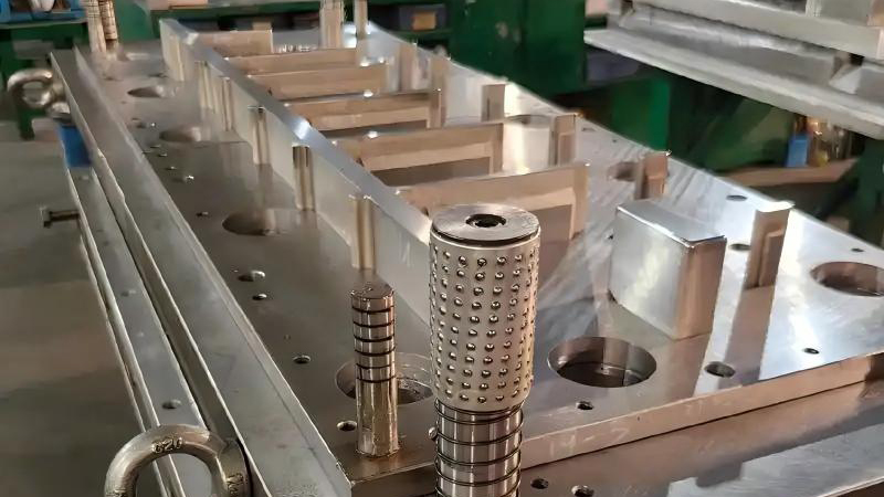
Fine blanking die showing V-ring impingement ring cross-section and pressure plate detail

V-Ring Cross-Section

V-Ring Punch Sheet

Typical V-ring cross-section showing the triangular profile that penetrates the sheet metal surface to create a plastic deformation zone.

Pressure Distribution Pattern

Die CenterEdge
Lowest: Under punch (pure compression) Highest: At V-ring root (triaxial stress)

The pressure distribution peaks at the V-ring root where triaxial compressive stress prevents material flow. Under the punch center, pressure is lower because the material is constrained by the die opening from below.

Force System

The Three Forces of Fine Blanking

Fine blanking requires three independently controlled forces acting simultaneously on the workpiece. Each force serves a distinct purpose and must be balanced for optimal results. The interaction of these three forces creates the hydrostatic stress state that suppresses fracture and produces the characteristic clean shear zone.

Blanking Force

60-70%

The main punch force that drives the punch through the material. Calculated as perimeter times thickness times shear strength, 0.7-0.9 times the material's ultimate tensile strength. This force must overcome the material's resistance to shear deformation.

V-Ring Force

25-35%

The clamping force from the impingement ring that locks the material ~the punch perimeter. Prevents lateral material flow and creates the triaxial stress state. Must be high enough to seal the material but not so high as to cause excessive V-ring indentation.

Counter-Pressure

5-10%

The upward force from the ejector plate that supports the material from below during shearing. Keeps the material flat and under compression, preventing the lower surface from initiating fracture. 5-15% of the blanking force.

The force ratio varies with material thickness and strength. For thin materials (under 3 mm), V-ring force percentage can be higher. For thick materials (over 8 mm), blanking force dominates. HS-FINEB presses feature independent hydraulic control of all three forces, allowing operators to optimize the balance for each material and part geometry.

Edge Quality

Shear Zone Formation and the Four-Zone Edge

The edge of a fine blanked part consists of four distinct zones, each formed by different mechanisms during shearing. Understanding these zones helps engineers specify fine blanking for edge-critical applications.

Edge Zone Composition (Cross-Section View)

Rollover
5-10%
Clean Shear
85-100%
Fracture
0-5%
Burr
Rollover Zone: Created by plastic deformation as the punch first contacts the material. The top surface deforms downward before shearing begins. Height is 5-10% of thickness in fine blanking versus 15-25% in conventional stamping.
Clean Shear Zone: The smooth, perpendicular surface created by clean shearing under hydrostatic compression. In fine blanking this zone reaches 85-100% of material thickness. In conventional stamping it is only 30-50%.
Fracture Zone: The rough, torn surface that appears when the material finally separates. In fine blanking this is minimized to 0-5% of thickness. In conventional stamping it dominates the edge at 40-60%.
Burr: A thin ridge of material pushed outward at the shear line. Fine blanking produces minimal burr (0.02-0.10 mm) that is easily removed in the integrated deburring station.

The dominance of the clean shear zone is the defining characteristic of fine blanking. In conventional stamping, 5-10% clearance allows the material to bend and fracture. In fine blanking, 0.5-1.0% clearance combined with the three-force system maintains compressive stress that prevents fracture initiation, producing a smooth surface with minimal rollover.

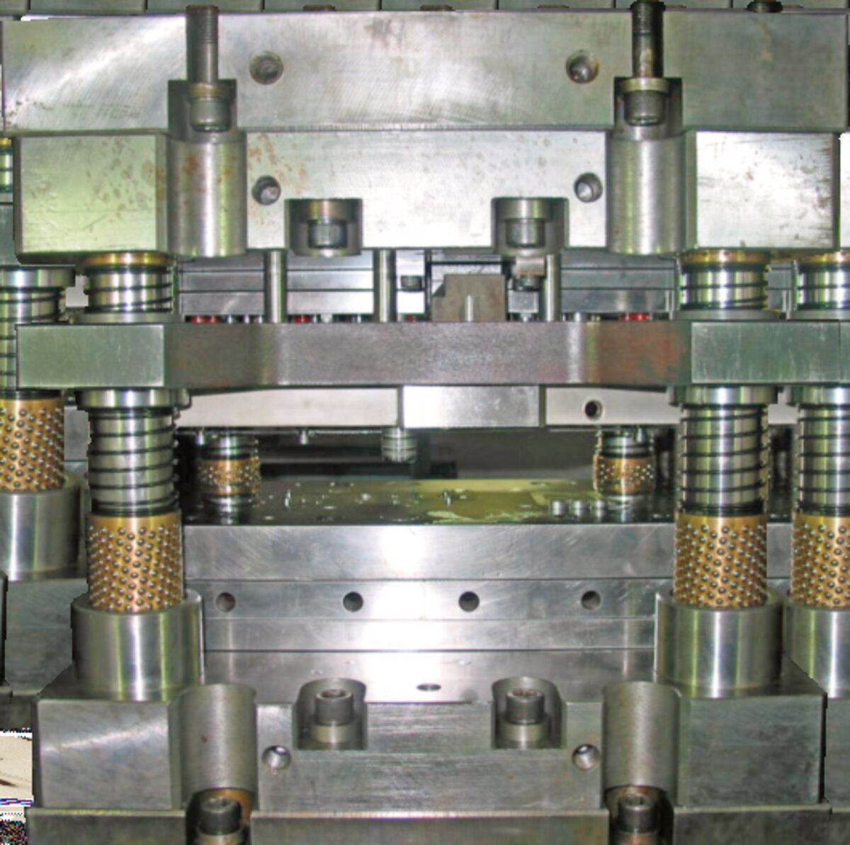
Close-up cross-section of fine blanking die showing shear zone formation and V-ring geometry

Cross-section detail of fine blanking die showing punch, die, V-ring, and counter-pressure ejector arrangement

Comparison

Fine Blanking vs Conventional Stamping

The fundamental difference between fine blanking and conventional stamping lies in die construction and force system. A conventional stamping die has only a punch and die with 5-10% clearance per side. The material bends and fractures when tensile stress exceeds fracture strength, producing significant rollover, small shear zone, large fracture zone, and substantial burr.

Conventional Stamping Edge

Rollover: 15-25% of thickness

Shear zone: 30-50% of thickness

Fracture zone: 40-60% of thickness

Burr: 0.1-0.3 mm

Clearance: 5-10% per side

Forces: Single punch force only

Fine Blanking Edge

Rollover: 5-10% of thickness

Shear zone: 85-100% of thickness

Fracture zone: 0-5% of thickness

Burr: 0.02-0.10 mm

Clearance: 0.5-1.0% per side

Forces: Blanking + V-ring + Counter-pressure

Fine blanking dies are more complex than conventional stamping dies, including punch, die, pressure plate with V-ring, counter-pressure ejector, and stripper. The die clearance is an order of magnitude smaller, requiring higher manufacturing precision. The press must deliver three independent forces with precise timing. However, the elimination of secondary machining makes fine blanking more economical for precision parts when annual volumes exceed 50,000 pieces.

Process Control

Parameters That Determine Edge Quality

Six process parameters control the quality of a fine blanked edge. HS-FINEB process engineers work with customers to develop parameter sets for each new part using simulation and empirical testing.

Punch-to-Die Clearance

The radial gap between punch and die, 0.5-1.0% of material thickness per side. Smaller clearance increases shear zone percentage but raises punching force and die wear. For materials over 6 mm, clearance may be increased to 1.0-1.5% to prevent excessive tool loading.

Punch Speed / Shear Rate

The velocity of the punch during the shearing stroke, 5-25 mm/second. Higher speeds reduce shear zone percentage in some materials due to adiabatic heating and strain rate effects. Slower speeds improve edge quality but reduce production rate.

Lubrication System

High-pressure lubricant (typically chlorinated or sulfurized oil) is injected between punch and material to reduce friction and prevent galling. Lubrication pressure is 20-60 bar. Insufficient lubrication causes punch adhesion, galling, and reduced tool life.

Material Thickness & Properties

Fine blanking is viable for materials from 0.5 mm to 16 mm thickness. Material hardness, grain size, and anisotropy affect shear zone formation. Annealed materials with fine grain structure produce the best results. Pre-hardened steels require higher forces and produce smaller shear zones.

The interdependence of these parameters means changing one variable requires compensating adjustments to others. HS-FINEB provides process parameter documentation with each die delivery, and our field service engineers assist customers with optimization during commissioning.

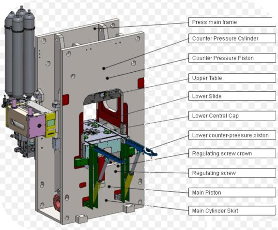
Fine blanking press structure showing force cylinders, die set, and feeding system integration

HS-FINEB fine blanking press showing integrated three-force hydraulic system and precision die set

See Fine Blanking in Action at Our Facility

HS-FINEB welcomes customers to visit our factory in Jingzhou, China for live demonstrations of the fine blanking process. Watch how the V-ring, punch, and counter-pressure forces interact in real time, and examine edge quality on parts produced from your material specification.

💬