💬 WhatsApp Chat

Three-Force Control in Fine Blanking: Blanking, V-Ring & Counter-Pressure

Fine blanking distinguishes itself from conventional stamping through a sophisticated three-force control system. Unlike a single-blanketing-force stamping press, a fine blanking press simultaneously applies three independent hydraulic forces — blanking, V-ring impingement, and counter-pressure — each governed by its own circuit, pump, and proportional valve. This triple-force architecture is what produces the characteristic 100% smooth shear edge, tight tolerances, and minimal die roll that define fine blanked parts.

Fundamentals

What Is the Three-Force Control System?

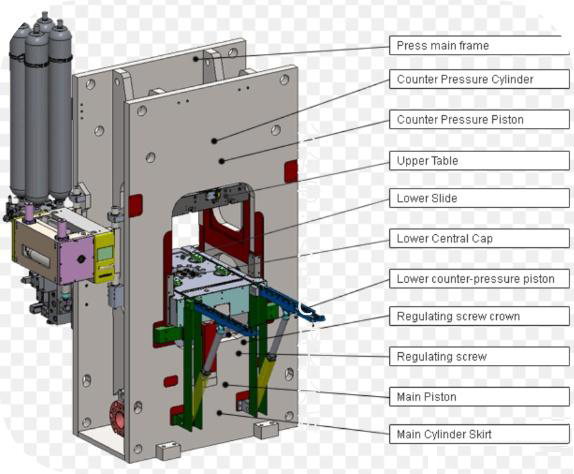
The defining technical distinction between a fine blanking press and a conventional stamping press lies in the simultaneous application of three precisely controlled forces. The blanking force, generated by the main hydraulic cylinder, drives the punch through the material to produce the cut. This is the primary cutting action, typically set at 50–100% of the press’s rated tonnage depending on material thickness, shear strength, and cutting perimeter.

The V-ring impingement force is applied by an annular V-ring surround that surrounds the cutting contour on the guide plate. Before the punch contacts the material, the V-ring presses into the strip surface, creating a ring of compressive stress that holds the material flat against the die. This impingement prevents lateral material flow during cutting, which is the primary cause of the tear zone in conventional stamping. Without V-ring engagement, the material would bend and tear rather than shear cleanly.

The counter-pressure force, also called ejector force, is applied from below the die by an opposing cylinder. This upward pressure resists the downward cutting motion and serves two functions: it controls die roll (the plastically deformed zone at the cutting edge) by maintaining compressive stress through the material thickness, and it ejects the finished part from the die cavity after the cutting stroke completes. Each of these three forces is generated by a separate hydraulic circuit with its own pump, valve manifold, and cylinder, allowing fully independent adjustment and monitoring.

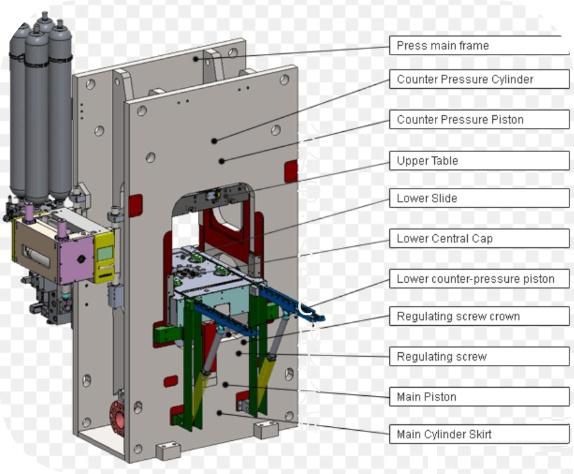
Cross-section diagram of a fine blanking press showing the three-force hydraulic system with blanking cylinder, V-ring impingement, and counter-pressure cylinder
Hydraulic Architecture

Force Generation and Control Components

Blanking Force (Main Ram)

The blanking force is generated by the main hydraulic cylinder, the largest cylinder in the press. A proportional directional valve controls flow and pressure, allowing the PLC to ramp force up and down with precision. Blanking force typically operates at 50–100% of rated tonnage; for example, an HF-650 rated at 650 tons may use 350–650 tons depending on the part. The main cylinder bore diameter, working pressure (typically 250–300 bar), and pump displacement determine the maximum available force.

V-Ring Impingement Force

The V-ring force is generated by an annular cylinder that surrounds the punch on the guide plate. This cylinder is independent from the main ram, with its own proportional valve and pressure transducer. V-ring force is typically set at 20–40% of the blanking force, calibrated to the material thickness and tensile strength. The V-ring creates a compressive stress field that prevents material flow lateral to the cutting direction, which is essential for achieving a 100% smooth shear zone without tear.

Counter-Pressure Force

The counter-pressure force is generated by an opposing cylinder mounted below the die, pushing upward against the cutting direction. It operates at 10–30% of the blanking force and has its own proportional valve, pressure sensor, and hydraulic circuit. The counter-pressure controls die roll depth (the plastically deformed zone at the cutting edge) and ejects the part after the cut. Higher counter-pressure reduces die roll but increases punch load; the setting is optimized per material and part geometry.

Force Synchronization

The press PLC coordinates all three forces within a 5-millisecond control loop. Proportional valves on each circuit respond to real-time feedback from pressure transducers, and the PLC adjusts valve signals to maintain each force within its target band throughout the stroke. This closed-loop synchronization is what distinguishes a true fine blanking press from a modified stamping press — without independent, real-time control of all three forces, the process cannot produce fine blanked quality.

Precision Engineering

Force Accuracy and Repeatability

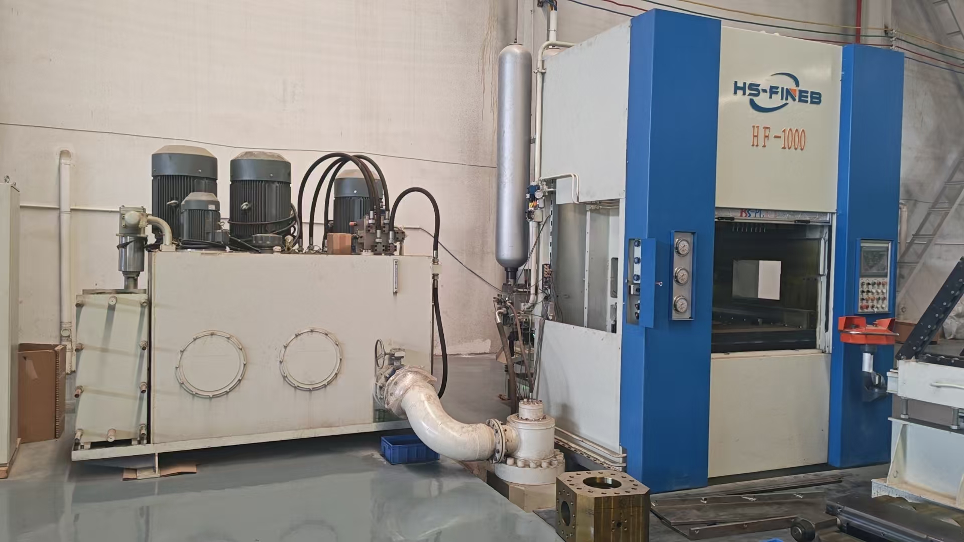
Real fine blanking press hydraulic system showing proportional valve manifold, pressure transducers, and three independent hydraulic circuits

Closed-Loop Control Achieves ±2% Force Accuracy

Fine blanking requires ±2% force accuracy on all three circuits. This is achieved through closed-loop proportional valve control: each hydraulic circuit has a pressure transducer mounted directly on the cylinder or valve block, feeding real-time pressure data to the PLC at sampling intervals of 1–2 milliseconds. The PLC compares actual pressure to the setpoint and adjusts the proportional valve current to correct any deviation within 5ms.

The effect on edge quality is direct and measurable. Consistent V-ring force ensures uniform material constraint across the entire cutting perimeter, eliminating localized tear zones. Consistent counter-pressure produces uniform die roll depth around the part circumference. Consistent blanking force maintains a steady cutting speed that produces the smooth shear surface. When all three forces repeat within ±2% stroke after stroke, the result is part-to-part consistency with no dimensional variation — the hallmark of a properly configured fine blanking press.

Force drift over time is detected by the monitoring system. If pressure transducers detect a trend beyond the ±2% band, the PLC logs an alarm, prompting inspection of valve wear, seal degradation, or pump efficiency loss. This predictive approach prevents quality degradation before it reaches the part.

Cycle Sequence

Interaction During the Blanking Cycle

The three forces do not act simultaneously at full value throughout the cycle. Rather, they follow a precisely timed sequence controlled by the PLC, with each phase transitioning within 10 milliseconds. Understanding this sequence is essential for die setup, force optimization, and troubleshooting part defects.

Phase 1 — V-Ring Engagement: The slide approaches the material at fast closing speed. Just before the V-ring contacts the strip, the PLC switches to press speed. The V-ring impingement force ramps to its set value, compressing the material and creating the lateral constraint field. At this point, the blanking force is at zero and counter-pressure is at its holding value.

Phase 2 — Blanking Force Ramp-Up: Once the V-ring is fully engaged, the main ram cylinder begins applying blanking force. The punch penetrates the material, and force increases as the shear zone develops. The PLC monitors penetration depth and force curve, adjusting the proportional valve to maintain steady cutting speed. V-ring force remains at its set value throughout.

Phase 3 — Counter-Pressure Hold: As the punch penetrates deeper, the counter-pressure cylinder maintains its opposing force from below. This controls die roll on the die-roll side of the part and prevents the material from bulging upward. The counter-pressure set value is critical here — too low and die roll exceeds specification; too high and punch load increases unnecessarily, accelerating die wear.

Phase 4 — Blanking Completion: The material fractures along the full cutting perimeter, completing the shear zone. The main ram reaches bottom dead center, and the blanking force peaks momentarily before the PLC signals valve de-energization. The timing of this phase — from punch contact to fracture completion — is typically 50–200 milliseconds depending on material thickness and cutting speed.

Phase 5 — Ejection: The slide retracts, and the counter-pressure cylinder pushes the finished part out of the die cavity. V-ring force releases, and the strip advances for the next cycle. The entire sequence, from V-ring engagement to ejection, occurs in 1–3 seconds depending on stroke rate, material, and part complexity. Timing precision within 10ms across all phases is what guarantees consistency.

HS-FINEB Implementation

Three-Force Systems in HF Series Presses

All HS-FINEB fine blanking presses from the HF-200 (200 tons) to the HF-1200 (1,200 tons) feature independent three-force hydraulic systems as standard. Each force circuit has its own pump station, proportional valve manifold, pressure transducer, and safety relief valve, ensuring true independent control rather than a shared hydraulic supply.

The proportional valves are sourced from Bosch Rexroth, selected for their response time (<5ms) and repeatability (±0.5% of set pressure). The press PLC provides real-time force monitoring with digital readout of all three forces on the HMI screen, allowing operators to verify set values and monitor actual values during production. Force curves are logged and can be exported for quality documentation and process validation.

The V-ring force is adjustable per material thickness across the full range of 0.5–12mm, with the PLC storing force recipes for different part programs. When a die change occurs, the operator selects the stored recipe, and all three forces automatically set to the correct values — no manual adjustment required. This recipe-based force management reduces setup time from hours to minutes and eliminates the variability of manual force setting.

The HF-650, HF-800, HF-1000, and HF-1200 models additionally feature hydraulic die clamping, automatic lubrication, and integrated coil feeding systems, creating a complete fine blanking production cell with three-force control at its core. For applications requiring maximum precision — such as aerospace components, medical device parts, and automotive safety components — the three-force system delivers the edge quality, dimensional accuracy, and process repeatability that fine blanking demands.

HS-FINEB press control panel showing real-time three-force monitoring with proportional valve readouts for blanking, V-ring, and counter-pressure circuits

Need Expert Guidance on Your Fine Blanking Press?

Our engineers at HS-FINEB bring over 40 years of fine blanking expertise to every project. Whether you need a new press, refurbishment of an existing machine, or technical consultation, we are ready to help.

💬