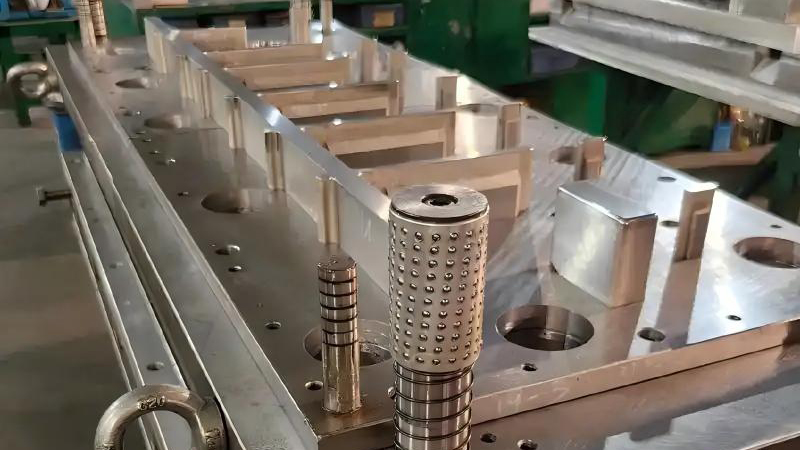
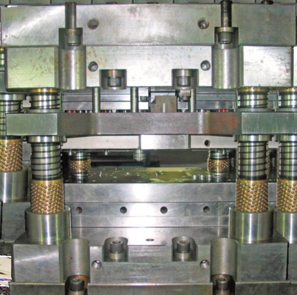
Fine blanking dies are the heart of the process — precision tooling manufactured through a multi-stage workflow of CNC machining, heat treatment, EDM, and precision grinding. This guide breaks down each manufacturing step, the equipment involved, the tolerances achieved, and how each process impacts final die accuracy and part quality.
Fine blanking dies are precision tooling that must withstand high blanking forces while producing parts with tight tolerances and clean shear edges. The manufacturing workflow follows a strict sequence: design (CAD/CAM) — CNC roughing (before heat treatment) — heat treatment to 60–64 HRC — EDM finishing (after hardening) — precision grinding (cutting edges) — assembly and fitting — tryout. Each stage is critical because once the die steel is hardened, conventional machining becomes impossible — only EDM and grinding can remove material with the precision required.
The total manufacturing time ranges from 4 to 8 weeks depending on die complexity, number of stations, and material specification. A simple single-station die for a washer-like part may take 3–4 weeks, while a progressive fine blanking die with 6 stations for a complex automotive seat recliner component can require 8–10 weeks. Die cost ranges from $8,000 for simple single-station dies to $50,000+ for complex multi-station progressive dies — the cost is driven by steel material (D2, PM30, or PM60 tool steel), complexity of part geometry, number of cutting edges, and V-ring configuration.
The sequence matters: CNC removes bulk material while the steel is soft (annealed at 28–32 HRC), heat treatment hardens it to working hardness, then EDM and grinding achieve final geometry and surface finish on the hardened material. Attempting to reverse this order — for example, grinding cutting edges before hardening — would result in dimensional distortion during quenching and render the die unusable.

CNC machining removes the bulk of material from the die block, creating the overall die plate geometry, drilling holes for fasteners and guide pillars, machining pockets for inserts, and roughing out the cutting edge profile before final EDM or grinding. This stage transforms a raw tool steel block into a near-net-shape die component. The goal is to remove 80–90% of the material that needs to come off, leaving a 0.2–0.5 mm allowance for EDM and grinding to achieve final accuracy.
CNC machining is performed on material in the annealed condition at 28–32 HRC, which machines cleanly with good chip formation and moderate tool wear. At this hardness, carbide end mills achieve reasonable material removal rates (150–300 cm³/min depending on machine rigidity and coolant delivery). Once the steel is hardened to 60–64 HRC, conventional CNC machining becomes impractical — tool wear is excessive and surface finish degrades. This is why all CNC roughing must be completed before the heat treatment stage.
Five-axis CNC handles complex die plates with 3D geometries and angled surfaces. Three-axis machines suffice for simpler flat pockets. After CNC, tolerance is approximately ±0.05 mm — not the final accuracy. Final die precision (±0.005 mm) is achieved by EDM and grinding after heat treatment.
Carbide end mills (4–12 mm for finishing, 16–32 mm for roughing) handle bulk material removal. Drill bits create fastener and guide pin holes. Face mills flatten reference surfaces. Through-spindle coolant manages heat and flushes chips. Tool wear is monitored — a 0.03 mm radius degradation shifts the machined surface by 0.02 mm.

EDM cuts fine details in hardened steel that cannot be machined by CNC after heat treatment. At 60–64 HRC, the die steel is too hard for carbide tools — EDM uses electrical sparks to erode material regardless of hardness, making it the only practical method for hardened tool steel.
Wire EDM uses a continuously fed brass wire (0.10–0.25 mm) to cut through-features: punch profiles, die openings, and ejector cutouts. The wire follows a programmed path, eroding material with sparks in deionized water. Accuracy is ±0.005 mm with Ra 0.4–0.8 µm. The wire threads through a pre-drilled start hole, producing a clean cut edge.
Sinker EDM uses a shaped graphite or copper electrode plunged into the workpiece to create blind pockets, V-ring grooves, and complex 3D cavities. The electrode is machined to the negative of the desired shape. V-ring grooves — the critical triangular rib for fine blanking — are produced by sinker EDM with a precision-machined graphite electrode matching the V-ring profile.
EDM creates a recast layer (5–15 µm) of re-solidified material that is harder and more brittle than the base. For non-critical surfaces, it is acceptable. For cutting edges and mating surfaces, it must be polished or ground away to prevent fatigue cracking.
Precision grinding is the final material-removal stage, delivering the dimensional accuracy and surface finish required on cutting edges, mating surfaces, and guiding elements. Four methods are used, each serving a specific purpose:
Surface grinding produces flat surfaces on die plates — the reference planes against which all other dimensions are measured. A horizontal spindle surface grinder with a cup wheel removes 0.01–0.05 mm per pass, achieving flatness of 0.005 mm over 300 mm and surface finish Ra 0.2–0.4 µm. The die plate top and bottom surfaces are ground parallel to serve as mounting references.
Cylindrical grinding is used for round components: punch outer diameters, guide pillars, and bushings. A cylindrical grinder rotates the workpiece against a traversing grinding wheel, achieving roundness of 0.002 mm and surface finish Ra 0.1–0.2 µm. Punch diameters are typically ground 0.5–1% of material thickness below the die opening diameter to create the blanking clearance — this clearance is critical for edge quality and must be uniform around the entire punch perimeter.
Profile grinding uses an optical profile grinder that projects a magnified silhouette of the punch onto a screen overlaid with a drawing template. The operator hand-feeds the grinding wheel to match the template profile, achieving accuracy of ±0.002 mm on complex punch cutting edge profiles. This method is essential for punches with curved or irregular profiles where CNC grinding cannot achieve the required precision. For gear punches, the profile grinder can maintain involute accuracy to AGMA class 8 or better.
Honing is used for holes requiring exceptional roundness and surface finish — guide pin holes and ejector pin holes. A hone uses expandable stones that rotate and reciprocate inside the hole, improving roundness to 0.001 mm and surface finish to Ra 0.05–0.1 µm. Honed holes ensure smooth, play-free sliding of guide pins, which is essential for maintaining punch-to-die alignment during the blanking stroke.
Die assembly brings together all machined components — die plate, punch, stripper plate, guide pillars and bushings, V-ring, and ejector system. The punch is fitted to the die plate with a specified clearance of 0.5–1% of material thickness (e.g., for 3 mm material, clearance is 0.015–0.030 mm). This clearance must be uniform around the entire cutting edge perimeter — uneven clearance causes burr formation, die wear acceleration, and edge quality degradation.
Hand fitting is where the die maker’s skill becomes irreplaceable. Even with precision CNC, EDM, and grinding, minute variations in geometry require hand fitting. The die maker applies spotting blue (Prussian blue) to the punch, inserts it into the die opening, and interprets the transfer pattern to identify high spots. Using hand scrapers and small stones, the die maker removes high spots incrementally until the blue transfer shows uniform contact — indicating uniform clearance. This process can take several hours to several days depending on die complexity.
Tryout is the first production run — the die is installed in a fine blanking press and test blanks are produced. The die maker inspects the first parts for edge quality (shear zone, tear zone, and burr height), adjusts V-ring force to optimize impingement, and tunes counter-pressure to control die roll. A well-fitted die produces parts with 80–100% shear zone, minimal tear zone, and burr height below 0.05 mm on the first tryout. If edge quality is substandard, the die maker adjusts parameters and re-tests.
Quality control documents the die’s dimensional conformance. A coordinate measuring machine (CMM) inspects all critical die component dimensions against the CAD model, generating a dimensional report with actual versus nominal values and tolerance compliance. Surface finish is verified with a profilometer on cutting edges and mating surfaces. The die is released to production only when all dimensions are within tolerance and the tryout parts meet the quality specification.
HS-FINEB maintains in-house die manufacturing capability with 5-axis CNC machining centers, wire and sinker EDM machines, surface and profile grinding equipment, and CMM inspection. This integrated capability allows us to control die quality from raw steel to finished tooling under one roof. Contact Helen at sales@fineblankingmachine.com for die design, manufacturing, or refurbishment inquiries.

HS-FINEB provides complete die design and manufacturing services — from CAD design through CNC, EDM, grinding, assembly, and tryout. Our in-house capability ensures quality control at every stage. Contact our engineers to discuss your die requirements.