💬 WhatsApp Chat

DfFB Hole Spacing Rules: Minimum Web Distances in Fine Blanking

The web material between holes in a fine blanked part must be thick enough to resist die breakage, support punch stability, and maintain dimensional accuracy. When webs are too thin, punches deflect, die sections fracture, and part flatness deteriorates. This guide establishes minimum web distances for fine blanking hole patterns, based on production data from HS-FINEB’s 40 years of die design experience.

Web Thickness

Why Hole Spacing Matters in Fine Blanking

In fine blanking, the web material between holes serves three critical functions. First, it provides structural support for the die section between punch cavities—when this section is too thin, it fractures under the compressive stress of the blanking stroke. Second, it resists punch deflection—thin webs allow adjacent punches to bend toward each other under load, causing dimensional drift and accelerated wear. Third, it maintains part flatness—thin webs deform plastically during blanking, creating dimensional errors that cannot be recovered in subsequent operations.

The physics is straightforward. During the blanking stroke, each punch exerts a force of 50 to 300 tons on the material. The web between two punches must resist this combined force without yielding. If the web thickness is less than 1.0 times the material thickness, the web material cannot support the die section, and progressive failure begins within the first few thousand strokes. The failure is not sudden—it accumulates through microcracking and plastic deformation until the die section fractures completely.

Beyond the immediate structural concern, hole spacing affects die cost. Complex hole patterns with thin webs require more expensive die construction methods—sinker EDM instead of wire EDM, segmented die inserts instead of monolithic dies, and additional assembly operations. A part designed with proper web distances can use a simpler, less expensive die construction while achieving the same dimensional results. The cost difference between a die for a well-designed part and a poorly-designed part with the same number of holes can reach 30 to 40 percent.

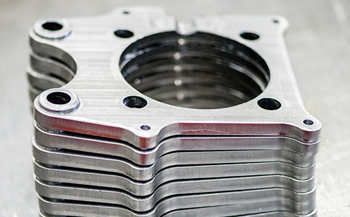
Fine blanked part showing hole pattern and web thickness between adjacent holes
Minimum Web Thickness

Minimum Web Thickness Rules

Between Two Holes

The minimum web thickness between two adjacent holes is 1.5 times the material thickness. For a 2mm part, this means a web of at least 3.0mm. Below this threshold, the die section between the two punch cavities becomes structurally unstable and will crack under cyclic loading. For high-strength steels above 600 MPa tensile strength, increase to 2.0t to account for higher blanking forces and greater die stress. The web should be measured at the narrowest point between the two hole edges, not center-to-center.

Edge to Nearest Hole

The minimum distance from the part edge to the nearest hole is 1.2 times the material thickness. For a 2mm part, this means at least 2.4mm from edge to hole center. Below this distance, the edge material tears irregularly during blanking, creating burr and dimensional variation at the part edge. The V-ring also requires sufficient material to function properly near edges—without enough material, the V-ring cannot generate the compressive stress needed for clean shear.

🔧

Blind Feature Walls

For blind holes, extrusions, and other non-through features, the minimum wall thickness is 1.0 times the material thickness. Blind features exert less force on the die because the material is not fully sheared, but the wall still must resist deformation. For extruded features deeper than 0.5t, increase the wall to 1.5t to prevent bulging. The material flow during extrusion creates lateral pressure that can deform thin walls, creating dimensional errors that are difficult to detect until assembly.

Material Type Effect

Softer materials such as copper and aluminum allow thinner webs—minimum 1.0t between holes—because they generate lower blanking forces. Harder steels above 500 MPa require 1.5 to 2.0t minimum web thickness to compensate for higher punch forces and greater die stress. Always adjust web thickness based on the specific material grade specified in the part drawing. Stainless steels are particularly sensitive due to their high work-hardening rate, which increases blanking force beyond what the nominal tensile strength suggests.

Failure Modes

Die Breakage and Failure Modes

Fine blanked parts showing hole patterns and web failure modes

How Thin Webs Cause Die Failure

Punch deflection is the most common failure mode for thin-web dies. When the web between two punches is less than 1.0t, the die section between the punch cavities lacks the stiffness to hold the punches parallel under load. The punches bend toward each other by 0.01 to 0.03mm, creating uneven clearance that accelerates wear on one side. Over 10,000 strokes, this deflection compounds until the punches contact and seize.

Die chipping occurs when the die section between two holes fractures under compressive stress. This is distinct from punch deflection—the die itself cracks, not the punch. The fracture typically initiates at the thinnest point of the web and propagates across the die section. Once a die section chips, the entire insert must be replaced, costing $500 to $2,000 depending on complexity and lead time for replacement inserts.

Material buckling affects the part, not the die. When the web is too thin, the material deforms plastically during blanking, creating a buckle or wave in the web area. This dimensional error cannot be recovered by flattening operations and results in scrap parts. In progressive dies, the web must also support the strip during transfer—thin webs tear during strip advancement, causing line stoppages and scrap rates of 5 to 15 percent.

Design Patterns

Design Recommendations for Common Patterns

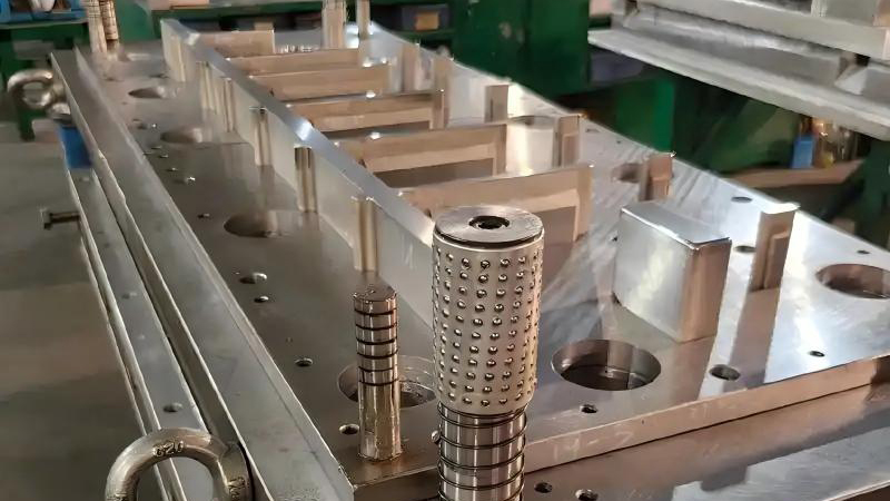
Fine blanking die showing hole pattern layout and punch configuration

Optimizing Hole Array Layout

For circular hole arrays, maintain a minimum 1.5t web between all adjacent holes and stagger rows to avoid creating a straight weak line across the die. A straight line of closely spaced holes creates a fracture path that the die will follow under cyclic stress. Staggering by just 0.5 times the hole diameter eliminates this risk while maintaining the same hole density.

For slot arrays, orient slots perpendicular to the primary loading direction. Slots oriented parallel to loading create long, thin webs that buckle under stress. Perpendicular orientation creates shorter, stiffer webs that resist deformation. If slot orientation is constrained by function, increase the web to 2.0t minimum to compensate for the unfavorable geometry.

Blind holes and extrusions require thicker webs than through holes—minimum 2.0t—because the material flow during extrusion creates lateral forces that push against adjacent walls. Complex geometries with intersecting features, irregular hole shapes, or tight tolerance zones should always be reviewed by the die maker before the drawing is finalized. HS-FINEB offers DfFB review service that examines hole spacing, web thickness, and feature interactions before die construction begins, typically identifying 3 to 5 modifications that improve manufacturability without compromising function.

Tolerance & Quality

Tolerance and Quality Implications

Proper hole spacing ensures consistent hole dimensions within ±0.02mm throughout die life. When webs are too thin, punch deflection causes hole diameter drift of 0.03 to 0.05mm, which may exceed tolerance limits on precision parts. This drift is gradual—the die produces in-spec parts for the first 5,000 to 8,000 strokes, then progressively drifts out of tolerance as punch deflection compounds. The drift is often undetected until assembly rejects begin, by which point thousands of out-of-tolerance parts may have been produced.

Proper spacing reduces die maintenance frequency by 40 percent. A die with adequate web distances typically requires resharpening every 15,000 to 20,000 strokes. A die with thin webs requires resharpening every 8,000 to 12,000 strokes due to accelerated punch wear from deflection-induced uneven clearance. Die life extends from 10,000 strokes with thin webs to 20,000+ strokes with proper webs. The maintenance frequency reduction also means less production downtime—each resharpening event requires 2 to 4 hours of press stoppage.

The cost benefit is clear. A one-time design adjustment—increasing web thickness from 1.0t to 1.5t—saves $3,000 to $8,000 in die maintenance over the production life of the part. This does not include the savings from reduced scrap rates, fewer line stoppages, and lower inspection frequency. HS-FINEB engineers can review your part drawings and recommend specific web thickness adjustments to optimize die life and quality. The review is fast, typically completed within 2 to 3 business days, and the recommendations can be implemented before die construction begins.

Review Your Hole Pattern Design

Our DfFB review examines hole spacing, web thickness, and feature interactions before die construction. Send your drawings and we will identify potential issues before they become costly die failures.

💬