💬 WhatsApp Chat

DfFB Burr Direction Rules: Controlling Burr Side in Fine Blanking

Every fine blanked part has a burr side—the surface where the punch exits the material, leaving a small raised edge. Burr direction affects assembly fit, sealing performance, and functional surface quality. This guide explains how die design controls which side carries the burr, what tolerances apply, and how to specify burr direction on part drawings to ensure the die maker produces exactly what the application requires.

Burr Side Control

What Is Burr Direction in Fine Blanking

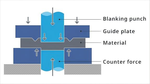
Fine blanking produces a small burr on the punch side of the part—the surface where the punch enters the material. The opposite side, the die side, has a clean shear edge with minimal die roll (the rounded tear zone at the cutting edge). This is a fundamental characteristic of the fine blanking process, determined by which component is the punch and which is the die.

Burr direction is not random—it is determined entirely by die design. In a standard fine blanking die, the punch is on top and the die is on bottom, producing burr on the top surface of the part. In an inverted die configuration, this is reversed. The die designer selects the configuration based on which surface must be the functional (burr-free) side. This decision must be made early in the die design process, as it affects die layout, tooling configuration, and strip design.

Burr height in fine blanking is typically 0.02 to 0.08mm, dramatically less than conventional stamping where burr heights of 0.1 to 0.5mm are common. This is one of the primary advantages of fine blanking—the near-burr-free edge quality. However, even this small burr can interfere with precision assembly, sealing, or sliding contact, making burr direction specification critical. Parts that function perfectly in prototype can fail in production if the burr direction is wrong, because the burr that was negligible in hand-assembly becomes an interference in automated assembly.

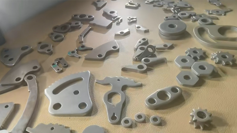
Fine blanked parts showing burr side and clean shear edge quality
Die Design Control

How Die Design Controls Burr Side

Punch Side Burr

The standard die configuration produces burr on the top (punch side) surface of the part. This is the default configuration for most fine blanking dies because it uses the simplest and most economical die construction. The bottom (die side) surface has the cleanest shear edge with minimal die roll. Specify this configuration when the bottom surface is the functional side—for example, when the bottom surface mates with another component or slides against a mating part.

Die Side Burr

An inverted die configuration produces burr on the bottom surface of the part. This requires special tooling—the die is mounted on top and the punch on bottom—and increases die cost by 15 to 25 percent. Use this configuration when the top surface must be the functional (burr-free) side and burr removal is not practical. The inverted configuration also affects part ejection and strip handling, requiring additional engineering in progressive die layouts.

🔧

Burr-Free Design

A shave or coining station in a progressive die can remove burr entirely. The shave station uses a small secondary punch that removes 0.05 to 0.10mm of material from the cut edge, producing a truly burr-free surface. This adds one station to the die and increases per-part cost by $0.02 to $0.05, but eliminates all burr-related assembly issues. The shave station must be precisely aligned with the blanking station to remove material uniformly.

Compound Die Configuration

In a compound fine blanking die, burr direction is determined by which component functions as the punch. The compound die can produce parts with burr on either side by reconfiguring the punch and die components. This flexibility makes compound dies ideal for prototyping and low-volume production where burr direction may need adjustment between batches. However, compound dies have lower production rates than progressive dies and are typically used for parts below 50,000 units per year.

Burr Height Tolerance

Burr Height Tolerance and Measurement

Fine blanking process showing shear edge quality and burr formation

Measuring and Controlling Burr Height

The target burr height in fine blanking is below 0.1mm. Most well-maintained fine blanking dies produce burr heights of 0.02 to 0.05mm at the start of die life. Burr height is measured using a micrometer or optical comparator, with samples taken every 500 strokes during production to monitor die condition. Statistical process control charts track burr height trends, allowing maintenance to be scheduled before burr exceeds specification.

Four factors affect burr height. Die clearance—the gap between punch and die—is the primary factor. Fine blanking uses very tight clearance, typically 0.5 percent of material thickness, which keeps burr minimal. As clearance increases with die wear, burr grows. Punch sharpness is the second factor—a dull punch tears rather than shears, increasing burr. Material hardness affects burr because harder materials resist clean shear. V-ring force controls material flow into the shear zone, and insufficient force increases die roll and burr.

Burr grows predictably over die life. A new die produces 0.02mm burr. After 10,000 strokes, burr reaches 0.05mm. After 20,000 strokes, burr may reach 0.08 to 0.10mm. When burr exceeds 0.10mm, the die requires resharpening to restore cutting edge sharpness and reduce clearance back to specification. This growth curve is why burr monitoring is an essential part of fine blanking quality control—without regular measurement, burr can exceed specification without being detected until assembly rejects occur.

Functional Surfaces

Design Rules for Functional Surfaces

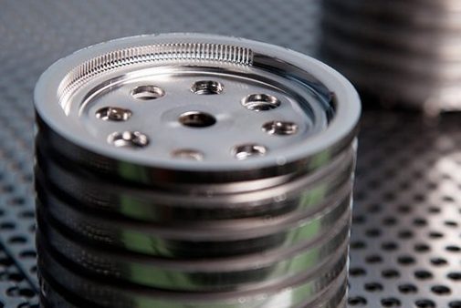
Fine blanked part detail showing functional surfaces and burr direction requirements

Burr Rules by Surface Type

Different functional surfaces have different burr sensitivity, and the drawing must specify the burr direction accordingly. Sliding surfaces—such as gear teeth, cam tracks, and guide rails—require the burr on the non-sliding side or complete burr removal. A 0.05mm burr on a sliding surface creates friction, accelerates wear, and can cause galling under load. For gear teeth, specify the die side as the contact surface to ensure the cleanest shear edge engages the mating gear.

Sealing surfaces are the most burr-sensitive application. Any burr on a sealing surface—whether for O-rings, gaskets, or metal-to-metal seals—will create leak paths. Specify complete burr removal for all sealing surfaces, and include a deburring requirement note on the drawing. The deburring method (vibratory, thermal, or machining) should be specified based on the seal type and tolerance. For metal-to-metal seals, specify a surface finish requirement in addition to burr removal.

Threaded holes present a special case. Burr from the blanking operation can interfere with subsequent tapping or thread forming, causing tap breakage and thread quality issues. Design the burr away from the threaded hole whenever possible—if the hole is on the die side, the burr will be minimal and tapping proceeds cleanly. Assembly mating surfaces should have the burr on the non-critical side. If both sides are mating surfaces, specify a deburring operation. The cost of deburring ($0.02 to $0.30 per part depending on method) is far less than the cost of assembly rework or field failure from burr interference.

Burr Removal & Mistakes

Burr Removal Strategies and Common Mistakes

When the design cannot avoid burr on the functional side, three removal strategies are available. Vibratory deburring costs $0.02 to $0.05 per part and removes burr from all edges simultaneously—ideal for complex geometries. Belt sanding costs $0.05 to $0.10 per part and provides controlled burr removal on specific surfaces, suitable for parts with mixed burr requirements. Precision machining (milling or turning) costs $0.10 to $0.30 per part and removes burr to tight tolerances, used for sealing and precision mating surfaces. The choice depends on part geometry, tolerance requirements, and production volume.

Three common mistakes account for most burr-related production problems. First, not specifying burr direction on the drawing—the die maker must guess, and there is a 50 percent chance the burr ends up on the wrong side. Always specify the burr side using a standard symbol or note on the part drawing. Second, specifying an impossible burr-free requirement without adding a deburring operation—fine blanking produces near-zero burr but not truly zero, and a burr-free specification requires either a shave station or a post-processing deburring step.

Third, ignoring the effect of burr on subsequent assembly operations—a 0.05mm burr that seems negligible on the drawing can cause significant assembly interference, particularly in press-fit and sliding-fit applications. HS-FINEB’s DfFB review includes burr direction analysis for all functional surfaces. Our engineers examine each surface on the part drawing, identify the required burr side based on function, and configure the die accordingly. This review is included at no additional cost with every die design order. Contact our engineering team to schedule a DfFB review for your part drawings.

Specify Burr Direction with Confidence

Our engineers analyze every functional surface on your part drawing to determine the correct burr side. Contact us for a DfFB review that ensures your die produces parts ready for assembly.

💬